Parallel Relations
Parallel/Hor./Vert./Advanced
There are two input fields for the parallel relations in the Define a plate contour dialog.

In the left field, enter the parallel value itself, usually a positive number. The parallel direction is the side where you have selected an item. If you have selected a plate in plan view, this means that the parallel line points outward. If you select Hor. or Vert., the relation will be shifted in a horizontal or vertical direction.
Entering a value in the right field means that the relation is slanted with respect to the selected item, and it is a straight line..
The distance in the left input field applies to the intersection of the previous relation with the current relation. The distance in the right input field applies to the intersection of the next relation with the current relation. No parallel value can be specified in relation to a border line.
Advanced Options
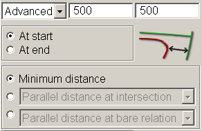
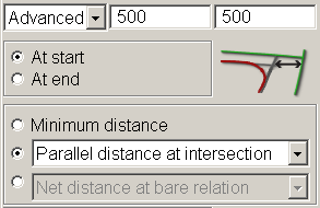
Some extra features are available when both parallel values are used. When you select Advanced, the panel is extended with some extra options. Both at the start of the relation and at the end of the relation the parallel distance can be entered independently. This can be achieved by selecting At start or At end.
Three main ways in defining a distance are available. It is about Minimum distance, Distance at intersection and Distance at bare relation. These ways are explained below.
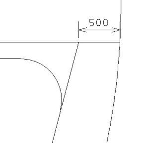
Minimum distance: In some cases the minimum distance between the contour and the related part is known. In most cases this will be at the involved round of curvature. In some cases, when the distance only decreases (e.g. because the other distance is smaller), then this distance will not really be the minimum distance but the distance of the start (or end) of the contour to the relation.
The image below shows the advanced part of the panel when Minimum distance is used.
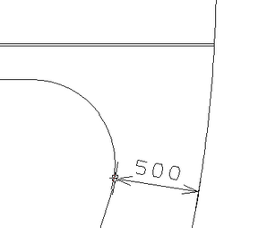
This will result in a plate like shown in the example below.
Distance at intersection: The distance at intersection point of the involved relation with the previous or next relation is the default way used at calculating parallel lines. The image below shows the advanced part of the panel when Distance at intersection is used.
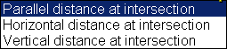
Now there are three variants for calculating as the option menu in the image below shows. When you select Horizontal distance at intersection or Vertical distance at intersection, the relation will be shifted in a horizontal or vertical direction.
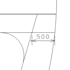
This will result in a plate like shown in the example below.
Distance at bare relation: In some cases the parallel distance is known at the intersection of the previous (or next) related item. In the examples shown in this section, the previous relation has a parallel distance to the deck upwards. The distance to the hull line is known at this deck. So bare relation means relation without its parallel distance. The image below shows the advanced part of the panel when Distance at bare relation is used.
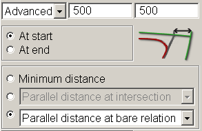
In this case there are three choices in defining the parallel distance:
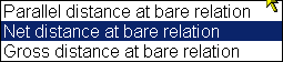
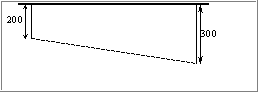
The first one, parallel distance, just means the parallel distance to the related item. Take our example again. Then the second one, net distance, is the distance between the intersection of the deck with the hull line and the intersection point of the parallel line (th the hull) and the deck. Gross distance means that this distance is measured along the deck. If this is for example a hull line, then it will differ from the net distance.
Using this variation of parallel distance will result in a plate like shown in the example below.