Relation properties
There are a few options available for selection when creating or modifying relations depending on the current situation. The given options and the default values are given for different situations below:
For a relation to a profile or shell frame in plan view or to a hull line:
-
Complete relation (default)
-
1 vector
The 1 vector option for a profile is only useful for a bent profile in bulb view.
For a relation to a plate in plan view:
-
Complete relation
-
1 vector (default)
-
Contra parallel
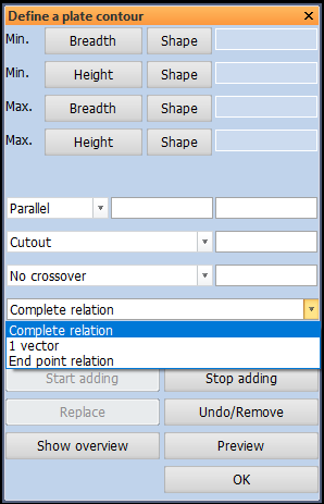
For a relation to a plate in cross section:
-
Complete relation (default)
-
1 vector
-
End point relation
Note that a plate in cross section can also be a shell plate.
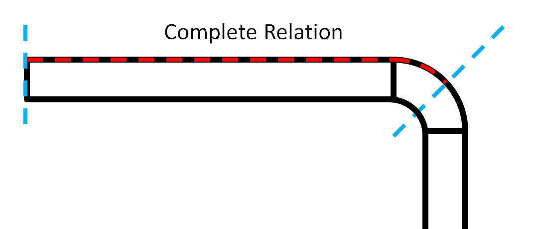
With this option, the relation follows the edge along entire plate in cross section, including its part of any knuckles. A plate will include up to the midpoint of any associated knuckles, as shown in the image below. The complete relation, shown with a red dashed line, will be on either the thickness or the molded side of the plate until the plate edges, shown with blue dashed lines.
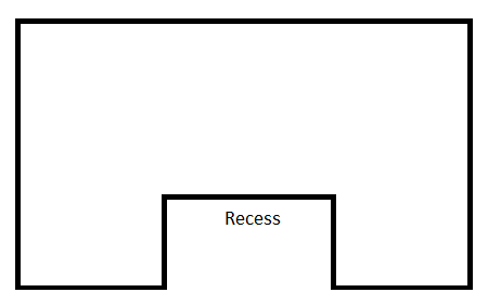
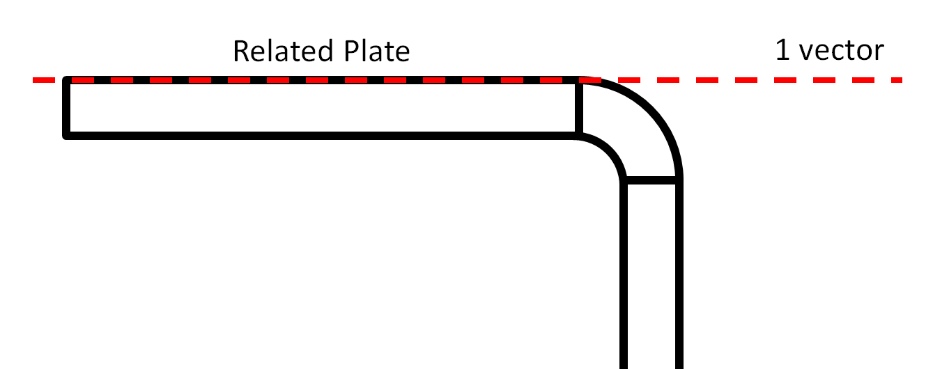
The option '1 vector' is useful for selecting plates in plan view and hull lines, for the part of the hull line which is horizontal, for example. This option does not work for a recess in a plate.
The specified vector will form the relation along the vector direction at either the thickness or molded side of the plate for a plate in cross section.
In plan view, the option for 'Contra parallel' is available. This option is useful for defining a relation on the opposite side of the part being created from the part that it is related to. This option requires the user to select the relation, then specify 'Contra parallel' and then enter a distance which the far side of the created part will be made from the related part. The image below represents how the use of the option 'Contra parallel' allows the user to create a relation on the opposite side of the new part from the part which it is related to.
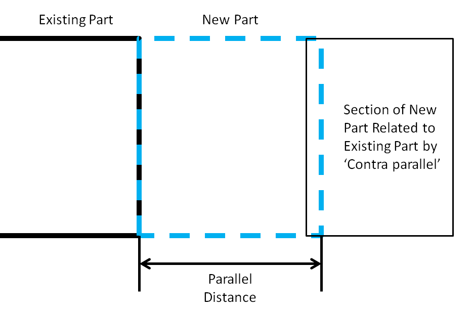
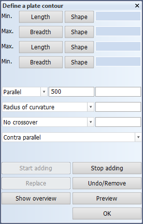
In the second image, the value of 500 entered beside parallel specifies that the Contra parallel relation should be placed at a distance of 500 from the existing plate.
End point relation is a relation option you can use when creating or modifying a plate in cross section. You can specify any end point of another plate as one of the relations of the new plate while creating the plate contour. The end point relation can be defined by indicating a direction relation (angle relation or extension) or a point relation (another end point or crossover). If an angle relation is not specified, the end of point relation is by default perpendicular to the end of the plate (that is, at an angle of 90°).
Below you can see an example of how to define an end relation by specifying angle relations.
Select end points
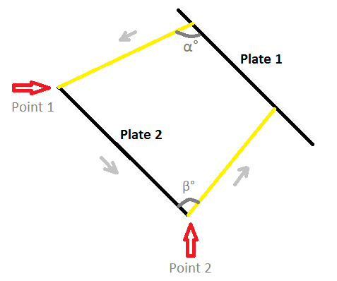
In order to create a new plate between Plate 1 and Plate 2 as on the example pictured, follow the steps listed below:
- Select Plate 1 relation by clicking right next to Plate 1.
- Define the desired angle from Plate 1 to Plate 2 by adding a value to the Angle to relation. In the image this angle is marked as α.
- Choose end point relation in the drop down menu and select one of the end points of Plate 2. In the image this point is marked as Point 1.
- Select Plate 2 relation by clicking right next to Plate 2.
- Choose end point relation in the drop down menu and select the other end point of Plate 2. In the image this point is marked as Point 2.
- Define the desired angle from Plate 2 to Plate 1 by adding a value to the Angle from relation. In the image this angle is marked as β.
- You can preview your plate by clicking Preview. If you are content with the form of the plate, click OK. Your plate is ready.
When you select a plate to define an end point relation, keep in mind that your selection will affect the end point you clicked the closest to with your mouse. In the image below (Fig. 3.) clicking closer to Point 1 would select it as an end point.
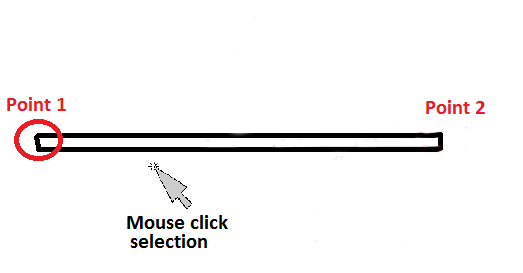
Holes and gaps will not be considered as end points in this relation.
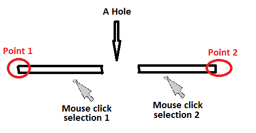
As pictured above, the system always considers the end point closest to the place where you clicked with your mouse, regardless of how close you click to the hole. Point 1 will be selected if you select the plate at the point marked with "Mouse click selection 1". Similarly, Point 2 will be selected if you select the plate at the point marked with "Mouse click selection 2".
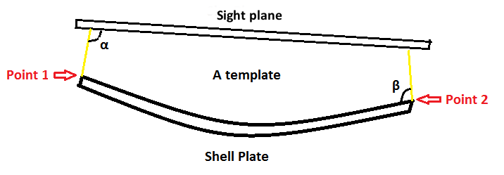
Using end points to draw templates
If one of the plates consisting of the end point relation is a plate in sight plane and other is a shell plate, the templates will be drawn exactly between them. See the image below for details.
Limitations
If a knuckle is presented as an arc then the knuckle cannot be indicated as a plate in a cross sectional relation. This can limit the functionality of the 'end point relation' option if the knuckle is the main part of a plate.