Creating slanted brackets between profiles
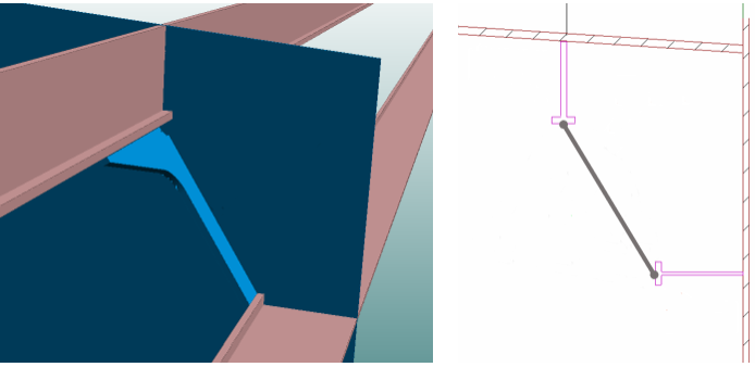
Slanted brackets can be created between two profiles, including shell frames and face plates, which have parallel base lines. These brackets can be placed in plan view and in cross-section, and they have topological connections to the related construction. The plane of these brackets is situated between the top sides of the related two profiles, at the molded side.
Note: To be able to place a bracket in cross-section, the planview variable must be defined in Label 1 of the bracket type file. The value, either 1 or 2, defines whether the related part in plan view is the 1st or 2nd relation of the bracket (planview=1 or planview=2).
Prerequisites
Not all bracket types can be added between two profiles. The bracket type must have 3 relations. The first relation must be a plate in cross-section, the second and third relation must be a profile, shell frame or face plate.
To be able to place a slanted bracket between two profiles, the following line must be added to Label 1 of the bracket type macro of the bracket type that needs to be placed between two profiles:
SlantedPlane=3
Values other that 3 will deactivate this feature.
Bracket relations
Bracket relations in plan view
A slanted bracket between two profiles must have 3 relations when placed in plan view. The relations must be selected in the following order:
-
The 1st relation must be a plate in cross-section.
-
The 2nd relation must be a profile (or shell frame or face plate) in view.
-
The 3rd relation must be a profile (or shell frame or face plate) in view.
Important: The profiles (2nd and 3rd relations) must be completely within the visibility settings of the view or they cannot be selected.
Bracket relations in cross-section
Only the profiles (or shell frames or face plates) must be selected. The system selects the plate automatically.
Multiple profiles can be selected with the clump of conflict selection method (moving the mouse left or right while pressing the mouse button).
Bracket plane
The plane of the bracket is situated between the top sides of the related profiles, at the molded side.
Bracket thickness
The system determines the bracket's thickness direction automatically based on the thickness directions of the related profiles.
-
If the thickness directions of the profiles point towards or away from each other, the bracket's thickness direction is in the same direction.
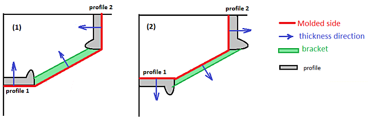
-
If the thickness directions of the profiles point to different directions, the bracket's thickness direction is the same as the thickness direction of the first related profile's (which is the bracket's 2nd relation).
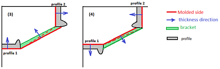
Note that in this case the plane of the bracket is rotated towards the molded side of the second related profile (3rd relation) to let the second profile support the bracket properly (indicated by the dashed red line in the picture).
Automatic adjustment of the bracket plane
It can happen that one of the arms of the bracket placed between profiles which are not parallel to each other is not fully connected to the one of the profile relations, and thus the bracket does not properly support the profile. To fix the gap in the connection, the system automatically adjusts the plane of the bracket.
When adjusting the bracket plane, the system shifts one the bracket's corners along the relation where the gap is, so that the bracket properly touches the profile.
-
When the bracket arms are of different length, the shift takes place in the shorter arm.
-
When the bracket arms are the same length, the shift takes place in the arm that goes along the 2nd profile relation.
If the amount of the shift needed to properly support the profile exceeds the threshold set in System Management > Construction > Brackets > Slanted Plane Shift Factor, the system shows a warning, but still creates the bracket. In this case it may be necessary to make adjustments to the construction.
By default, the threshold for the shift is the same as the body thickness of the profile along which the shift takes place.