Defining the plate border
The plate border is defined in the Define a plate contour dialog. The dialog looks slightly different for slanted plates. In 3D-Show, this dialog has been simplified.
A relation may be determined in various ways, such as by selecting a construction part, hull line, or a line or arc you have drawn yourself, for example. It is also possible to select a frame number or frame line or a grid value or grid line. You can also enter a border or shell limitation value in the Relations dialog. A selected item should normally be indicated at the side where you want to create the new plate, since the indicated side may influence the shape of the plate. So, never point exactly on a item.
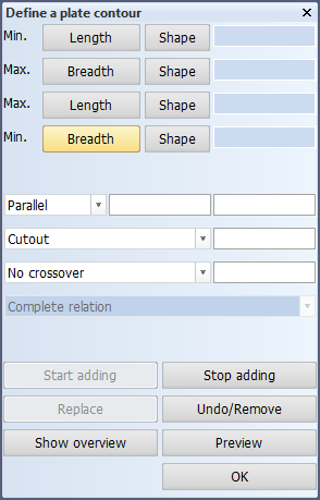
Apart from entry boxes for specifying minimum and maximum border values, the Define a plate contour dialog also contains buttons for specifying additional functions of relations and buttons for general operations. In the following description of the panel, the general way in which it works is explained first. Then several buttons are described. The dialog in the image below and the accompanying explanation apply to a cross-section. There are different minimum and maximum border values for other views.
When a new plate is created the relations of the plate contour can be selected directly in the graphics window or entered in the panel. If one or more relations have been selected it is possible to stop adding relations and to make changes on the already selected relations, in the same way as when modifying plates.
Changing the plate contour starts with selecting the plate. The relations that determine the plate contour are shown. Every part of the contour belongs to a relation. An overview of the relations is shown in a list and the relations panel is shown.
It is now possible to select a relation by pointing at the contour in the graphics window or by selecting one from the list. When a relation is selected by pointing at the contour it will also be selected in the list. When a relation is selected from the list the part of the contour belonging to this relation is highlighted. The selected relation can be changed or replaced or other relations can be added.
There are several reasons for indicating relations in the graphics window. This is shown by the hint. The reasons are:
- Indicating a construction part, auxiliary lines or arcs or hull lines as a new relation.
- Indicating a construction part, auxiliary lines or arcs or hull lines to replace a relation.
- Indicating a relation where to stop adding new relations.
- Indicating a relation where a modification is required.
If the list with relations is present it is kept up to date with the accepted relations. A relation is accepted when a new relation is created or another relation is selected or the Start adding, Stop adding, Compute or OK button is clicked. After removing a relation the list is also updated.
Actions
The functionality of the different action buttons is described below. See Modifying plates for a description of the sequence in which these buttons should be used. In general, a button is frozen when it should not be used.
The relations panel has a number of buttons. For every button the action is described below.
Start adding
After selecting a relation from the list or the graphics window new relations can be added after this one by clicking this button.
Stop adding
The adding of relations can only be stopped by clicking this button. This means that while adding no relations can be selected from the list or replaced and the OK button cannot be clicked. When the adding of relations is finished the relation where the addition ends must be selected. Because the adding of relations often starts and ends at the same relation, the relation where the adding starts is added to the list after the last added relation and highlighted. The relations panel is now temporarily completely frozen.
The relation where the adding ends can now be selected from the list or the graphics window. For the selection of this relation from the graphics window there is a preference for the relation suggested by the system over the relation where the adding started. If a relation is indicated at a place where other relations are present, which can also be selected, a list is shown of possible relations based on the indicated point. The selected relation is highlighted in this list. When a relation is selected from the list it is also highlighted in the graphics window. If the OK button belonging to this list is clicked, the last selected relation will be the ending relation.
Replace
If a relation is selected, while not adding relations, the values and such are shown in the panel. By clicking Replace this relation can be replaced by another relation (for example, a plate in section by another plate in section) by selecting this relation in the graphics window or entering a fixed limitation. If the selection fails the Replace button has to be clicked again before another replacing relation can be selected.
Note: A relation can also be replaced by a fixed limitation. In this case it is not necessary to click the Replace button.
Undo/Remove
When a relation is selected to be modified it can be removed by clicking this button. When relations are being added the last added relation is removed. If a relation has to be selected where to stop adding and a wrong selection is made then you can undo this selection with the Undo/Remove button and you have to select another relation. If the Replace button is clicked and a replacing relation has been selected then you can undo this replacement with the Undo/Remove button. If this button is clicked again you will be asked if the last selected relation should be removed. Only when confirmed this relation is removed.
Show overview
By clicking this button all relations are shown in a list. By clicking it again the list is removed.
Compute
When this button is clicked an attempt is made to compute the plate contour from the relations that have been entered. Also the last entered modification (e.g. a modification in parallel distance for the last selected relation) is included. If the computation succeeds the plate contour is shown in the same way as when the function for changing the plate contour is started. In case of an error or warnings the error messages are presented in a separate panel. For every error it shows which relation(s) are involved as much as possible. When clicking on the error message the relations are highlighted in the graphics window. This panel disappears when the Show overview button is clicked, this will also remove the list with the relations overview. After the computation a relation has to be selected before another modification can be made.
A new relation is specified when you select an item in the Graphics Window or click on one of the (Min.) Breadth, Shape, (Min.) Height, Shape, (Max.) Breadth, Shape, or (Max.) Height, Shape buttons. Then you can specify characteristics such as the border value (if you click on one of the Min or Max buttons), the parallel distance, the cutout or the radius of curvature, and the crossover.
When you indicate another item in the Graphics Window, one of the Min or Max buttons, the Accept current relation button, or the OK button at the end of defining the plate contour, the program accepts the relation. A selected or accepted relation is always shown with pen 6 in the Graphics Window. The default colour for this pen is yellow. The last selected or accepted relation can by deleted by clicking on the Remove last indicated relation button. This may be repeated all the way up to the first relation you have created.
By way of example, we will describe the procedure for creating a simple plate. The top of this plate borders on a deck, its left on a fixed value, and its right and bottom on the shell. The plate is situated on the SB side and does not cross CL.
After you have indicated the thickness and the type of material, the Relations panel is displayed on the screen. First click on the Min. Breadth button, then enter the breadth value. This specifies the hull line on the inside. The program accepts this value as the minimum breadth and freezes the breadth value. Then click on the deck below the plate. By clicking on the OK button, you confirm the deck line. The program then computes the plate border and draws it in the Graphics Window in so far as it has visible lines (in this case the minimum breadth limitation).
Below you will find a description of the function of each button and entry box in the Relations panel. In some cases, the description will be accompanied by an example.
Undo/Remove last indicated relation
Delete incorrect relations. This may be done up to and including the first characteristic of the plate border.
OK
When you click OK, the program accepts all relations you have specified and computes the plate.
While working in the Define a plate contour dialog, you can zoom in or out, for example, and perform various other operations. In 3D-Show you can also view the drawing from another angle, which is why this application has a button for returning to the current working plane in which the plate is being created.