Shifting items
To enter shift values the following dialog is used:
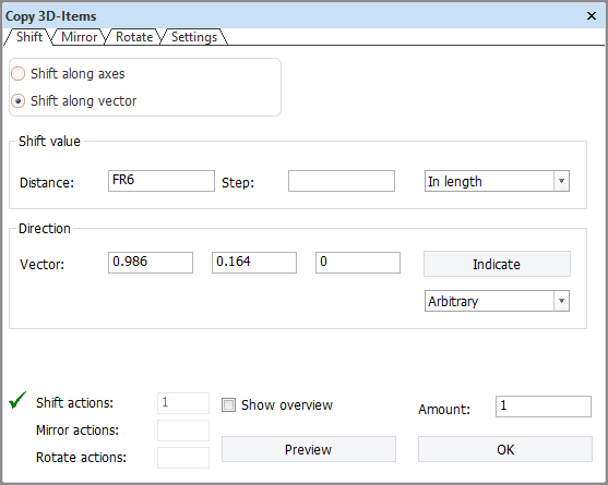
Shift along axes allows the user to enter shift values in all three directions at once. The toggle In slanting plane is only present in slanted views. Checking it will cause the system to automatically add extra shift values in other directions in order to keep the target position in the plane of the active drawing.
Shift along vector lets the user enter or indicate a vector defining the direction in which to copy. In slanted views the panel appears like this by default. The distance that is entered can be interpreted in several ways:
If the distance is to be measured in length, width or height the system automatically adds shift values in the other directions to achieve the direction defined by the direction vector. For example, see the figure below:
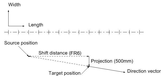
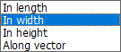
The entered shift value is FR6, but the direction vector dictates that there should also be a shift in width of 500 mm. The direction vector can be either typed in, indicated in the drawing or selected from the drop-down menu:
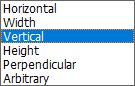
This down-down menu differs depending on the current view. Selecting Horizontal, Vertical, or Perpendicular will result in a 3D vector that corresponds with horizontal, vertical, or perpendicular in the drawing. Length, Width and Height can be used to define a vector in length, width or height, with components in other directions to keep the vector in the plane of the drawing (Height is not in the above example because this is the drop-down menu displayed in a slanted top view). In most cases Horizontal will correspond with Length and Vertical with Width or Height, but in perpendicular views the user can choose to have fixed length vertical for example, and then there is a difference. Selecting Arbitary from this menu will clear the direction vector, enabling the user to enter one.
If the user indicates a vector in the drawing by first clicking Indicate and then selecting some vector in the drawing, the direction of that vector is inserted in the panel. If no distance was specified in advance, the length of the indicated vector is inserted as the distance.
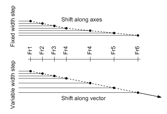
The difference between Shift along axes and Shift along vector is that using the user can copy in 3 directions at once, but the step size will be the same for each copy. This means that the copies are not necessarily on a straight line. This is illustrated in the figure below. The frame spacing is not constant. 6 Copies are made with a step in length of FR1. In the first case (Shift along axes) a step in width is also entered. In the second case (Shift along vector) only a step in length is entered. The difference is obvious: the copies along the vector are in a straight line, the others are not.