Basic position of flange cutouts
With the function "Construction/Create/Cutout around girder" it is possible to add a cutout around a plate in cross section with a flange. This function takes care of four standard variables which can be used in this special corner hole definition. This variables are R5 until R8. This sketch shows the meaning of these variables.
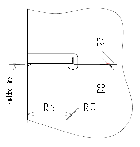
R5 = Faceplate thickness in X direction
R6 = Body size plate in X direction
R7 = Flange maximum width one side in Y direction (this can be negative or positive)
R8 = Flange minimum width other side in Y direction (this can be negative or positive)
Because of the fact that this cutout around a flange is a corner hole definition (type number 311 - 399) this type is not topologic in relation to this flange.
In most cases the shape of this hole is asymmetric. To solve this the I (R7IV7) statement is helpful to position the hole direction in Y direction. see example below:
0 0 0
0
LET V1=10
LET V2=30
LET V3=35
LET V4=40
LET V5=1
LET V6=-1
LET V7=1
LET V8=R7IV7
LET V9=V1*V8
LET VA=V2*V8
LET VB=V3*V8
LET VC=V4*V8
L 0 0 0 R7+VA
L 0 R7+VA R6+R5+V4 R7+VA
C ? ? V3*V6
L R6+R5+V4 R7+VA R6+R5+V4 R8*V6-VB
C ? ? V3*V6
L R6+R5+V4 R8*V6-VB R6-V2 R8*V6-VB
C ? ? V2*V6
L R6-V2 R8*V6-VB R6-V2 R8*V6
L R6-V2 R8*V6 V1 R8*V6
L V1 R8*V6 0 R8*V6-V9
L 0 R8*V6-V9 0 0
L 0 0 0 0
E 0 0 R6+R5 R8*V5