Basic position of cutouts and lugs
The type files with numbers 100–199 define the cutouts that may be created in plates or profiles. The type files are stored in the uitsp, uitsp3d and uitsp2d directories. Cutouts are attributes of the parts they are placed in. Type files in the range of 700–799 describe the lugs which can be related to cutouts. Once defined, the system correctly places the cutout in the drawing, or processes it for the various production functions.
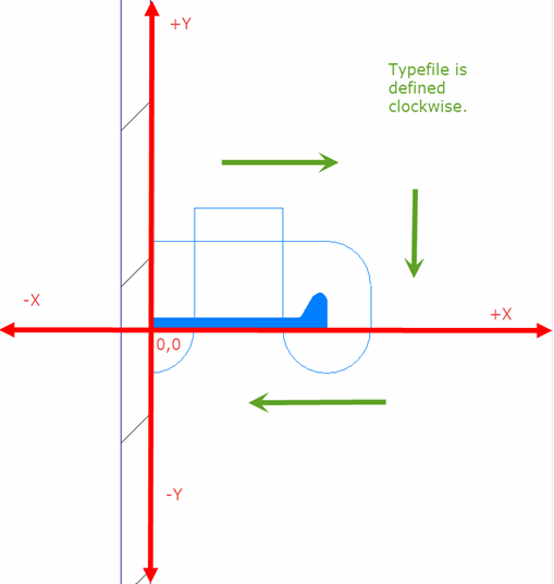
The attributes of cutouts are defined in a two-dimensional plane in the positive quadrant of the Cartesian coordinate system.
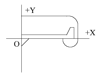
The profile is placed on its moulded side on +X axis so that the thickness of the profile is measured in the +Y direction from the origin (O). Hence, the cutout is related to the profile and its relation regardless of the view, that is, port side or starboard or looking forward or aft. The cutout is always defined clockwise.