Modifying a bracket type to create a new type
This help topic is the second part of the Bracket type tutorial. We create a new bracket type which is based on an existing one, bracket 748.
The first part of the tutorial is the Inspecting a bracket type file help topic where we trace the bracket contour line by line and look at some related type macro issues. The purpose of the first part is to understand how the bracket contour is defined. It is recommended that you go through that part before proceeding with this one. The type that we inspect is the same as the one we modify here.
We are using an existing bracket type 748 as the basis for the new bracket type.
Modifying the type
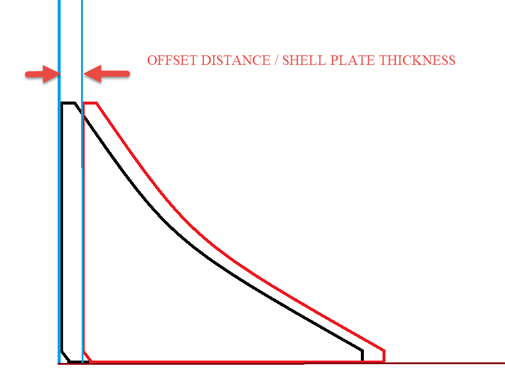
The new bracket type will be related to a hull line and placed so that the shell plate thickness is used as the offset distance for the bracket. We will define the bracket type so that the contour of the bracket shifts along both of its axes based on user input given for the shell plate thickness. The user input is needed here because we cannot use the shell plate thickness from a logistical field.
Consider the following:
-
Because we need to add the offset to the bracket so that only the position of the bracket shifts along the axis while the overall dimensions are retained, we must add the offset value as a user input function. If the input is zero or blank, the bracket should align itself to the shell plate without any offset.
-
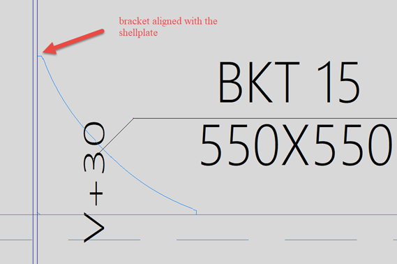
The bracket needs to be shifted only along one axis as shown in the image above. This means that the offset distance must be added to the coordinates perpendicular to the U axis and parallel to the V axis, so that if the user input for the offset distance is zero, then the bracket shifts back to its original location.
First we must define the question and the answer for the user input, and add an R variable for the user input value. This is done in the type macro (bracket<number>.cmd).
Then we must relate the newly created R variable to U and V axis variables. This is done in the type file.
Do the following:
-
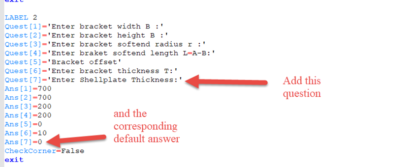
In the type macro, Label 2, add the following line for the question:
Quest[7]='Enter Shellplate Thickness: '
Then add the default answer to the question:
Ans[7]=0
Note that nothing is added to Label 4. Bracket standards are defined in Label 4, and because the shell plate thickness is a user input, standards cannot be used. This because to be able to enter the thickness value, the user must select free in the bracket type dialog, which makes the Standards selection unavailable.
-
In the type macro, Label 5, add variable R7 and link it to the user input variable [Ans7].
-
Save the changes to the type macro. Because we have modified the type macro, we need to delete the bracket<number>.tab file. This file must be deleted if any questions in the type macro are modified. The system will generate a new .tab file to replace the old one. If the file is not deleted, the system will show the bracket type input dialog according to the old type macro file. This file is located where the type file and the type macro files are located (in the brackets subfolder of the project norms).
-
In the bracket type file, relate the R7 variable, which contains the user input value, to the U and V variables. This is done by adding the UR variable to the #as2 section of the file. The UR variable is added to the VI variable.
Then edit the first line (status line) of the type file by changing the number of variables defined in the file from 17 to 18.
-
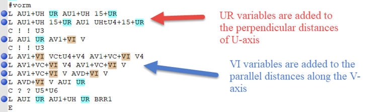
In the type file, #vorm (shape definition) section, add the UR and VI variables to the U axis and the and V axis (to the L lines). This way the offset distance is added to the coordinates perpendicular to the U axis and parallel to the V axis
-
Add UR variables to the perpendicular distances of the U axes as shown in the image below.
-
Add VI variables to the parallel distances along the V axis as shown in the image below.
-
-
Save the changes to the type file.
-
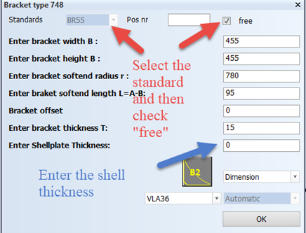
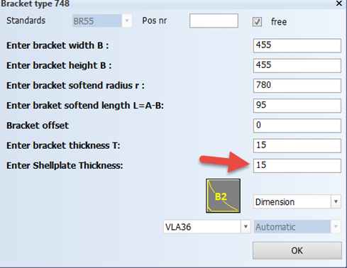
Create the bracket. Go to Construction > Brackets > Insert > in View. Select free in the bracket type dialog that opens. This disables the Standards selection and allows the user to enter or edit the inputs.
In the image above, 15 is the entered as the shell plate thickness. Once you click OK, you will see that the bracket is aligned with the shell plate as required. You can check this with both the snipe and the cutout.


If you create a bracket and do not want an offset with the shell plate, Ans[7]) must be set to zero by default.
However, you will see an error message saying that the bracket thickness is zero. The reason for this is that the question about the bracket thickness should always be asked last. In this case, we have asked the shell plate thickness last. Therefore, the bracket type file and type macro must be modified so that the bracket thickness comes last, and shell plate thickness (the user input), comes before the bracket thickness question. When we actually create the bracket, there should be no error if the shell thickness is filled zero by the user.