Face plates lines in user hole type files
Multiple face plates or face plates with a specified starting and ending point in user holes are possible by adding so called face plate lines to the type file of the specific user hole. These lines must be somewhere in the contour definition part of the type file where they define the starting and ending points of the face plates.
There are two kinds of face plate lines which exclude each other. So only one kind of line can be used in one type file.
Lines specifying one, two or four consecutive face plates.
With this kind of lines the starting and ending points of one, two or four face plates are defined of which the ending point of one is the starting point of the next.
The possible lines are: "F 1", "F 12", "F 124", "F 14", "F 2", "F 24" and "F 4".
For example the lines
L R2/V6-V5 R1/V6-V2 R2/V6-V5 R1/V6*V7+V2
F 1
deliver one closed face plate with the starting and ending point situated at the second point (last defined point before the F line) specified by the L line.
The lines
C R2/V6-V5-V2 R1/V6-V2 V2*V7
F 1
L R2/V6-V5 R1/V6-V2 R2/V6-V5 R1/V6*V7+V2
result in a starting/ending point which is equal to the first point specified by the L line.
The "F 2" line specifies one of the two points used for two face plates. It is a starting point for one of two face plates and the ending point of the other. In the same way "F 4" specifies one of the four points used as a ending point for one of four face plates and the ending point of the next.
If a certain point is to be defined as a starting/ending point for one "closed" face plate or the starting and ending point of two of a total of two face plates the "F 12" line has to be used. The line "F 124" has to be used if this specific point must also be used by two of a total of four face plates.

|
The first icon can be used to place one face plate and the point defined by "F 1", "F 12", "F 124" or "F 14" will be used as starting/ending point. |

|
The second icon will result in two face plates with starting/ending points defined by "F 12" or "F 124" and "F 2" or "F 24". In this case there have to be two F lines containing a 2. If however the type file does not contain F lines with a 2, one "closed" face plate will be placed. |

|
If the third icon is used, four face plates will be created and there have to be four F lines in the type file containing a 4, so "F 124" and/or "F14" and/or "F 24" and/or "F 4" otherwise one "closed" face plate will be created. |
There can only be one F line containing a 1 in the type file. Also there can only be two F lines containing a 2 and four F lines containing a 4.
Lines to define specific face plates.
The lines "F S <value>" and "F E <value>" are used to specify respectively the starting and ending point of a individual face plate. So the by these lines defined points are only used by one face plate. In the same way as with the lines for defining consecutive face plates for example the lines
L R2/V6-V5 R1/V6-V2 R2/V6-V5 R1/V6*V7+V2
F S
defines the starting point to be the second point of the vector defined by the L line.
The <value> is optional. It is used to specify a distance along a vector in the direction of the other endpoint of the face plate to where the face plate really starts. This can be a numeric value or a formula containing R and/or V variables. This distance can be traveled only along a line not along a circle. So only if the "F S" line is followed by a L line and the length of the vector defined by this line is large enough, a positive value will be handled. If a negative value is specified the line before the "F S" line must be a L line.
In the case of a "F E" line a positive value can be handled only is the previous line is a L line, while a negative value needs the next line to be a L line.
The value used in the "F S <value>" line can be different from the value used in the "F E <value>" line.
In this way a maximum of 9 specific face plates can be defined in one type file.
These face plates will be placed only when the icon for two or four face plates is selected otherwise one "closed" face plate will be created.
Gap
When face plates are defined with face plate lines for specifying one, two or four consecutive face plates, the function of the gap is the same as is in standard holes. If however the face plates are defined with "F S" and "F E" lines, a gap not equal to zero results in a shortening of the face plate. It will be shortened by half the gap value on each side.
| Note: A gap value overrules a possible specified value in the "F S <value>" or "F E <value>" lines. |
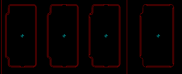
In the picture below, the face plates in the first three user holes are placed with respectively the first, second and third icon of the "Face plate in hole" panel. The type file of the corresponding holes contains only face plate lines of the first kind, for example (only the contour definition part of the type file is shown here):
L 0 R1/V6*V7 R2/V6*V7+V5+V2 R1/V6*V7
C R2/V6*V7+V5+V2 R1/V6*V7+V2 V2*V7
L R2/V6*V7+V5 R1/V6*V7+V2 R2/V6*V7+V5 R1/V6*V7+V3-V1
C R2/V6*V7+V5-V1 R1/V6*V7+V3-V1 V1
L R2/V6*V7+V5-V1 R1/V6*V7+V3 R2/V6*V7+V1 R1/V6*V7+V3
C R2/V6*V7+V1 R1/V6*V7+V3+V1 V1*V7
F 4
L R2/V6*V7 R1/V6*V7+V3+V1 R2/V6*V7 R1/V6-V3-V1
F 4
C R2/V6*V7+V1 R1/V6-V3-V1 V1*V7
L R2/V6*V7+V1 R1/V6-V3 R2/V6*V7+V5-V1 R1/V6-V3
C R2/V6*V7+V5-V1 R1/V6-V3+V1 V1
L R2/V6*V7+V5 R1/V6-V3+V1 R2/V6*V7+V5 R1/V6-V2
C R2/V6*V7+V5+V2 R1/V6-V2 V2*V7
L R2/V6*V7+V5+V2 R1/V6 0 R1/V6
F 24
L 0 R1/V6 R2/V6-V5-V2 R1/V6
C R2/V6-V5-V2 R1/V6-V2 V2*V7
L R2/V6-V5 R1/V6-V2 R2/V6-V5 R1/V6*V7+V2
C R2/V6-V5-V2 R1/V6*V7+V2 V2*V7
L R2/V6-V5-V2 R1/V6*V7 0 R1/V6*V7
F 124
The fourth hole below, contains face plates generated with the second or third icon of the "Face plate in hole" panel and a type file containing only lines of the second kind, for example (only the contour definition part of the type file is shown here):
L 0 R1/V6*V7 R2/V6*V7+V5+V2 R1/V6*V7
F E 20
C R2/V6*V7+V5+V2 R1/V6*V7+V2 V2*V7
L R2/V6*V7+V5 R1/V6*V7+V2 R2/V6*V7+V5 R1/V6*V7+V3-V1
C R2/V6*V7+V5-V1 R1/V6*V7+V3-V1 V1
L R2/V6*V7+V5-V1 R1/V6*V7+V3 R2/V6*V7+V1 R1/V6*V7+V3
C R2/V6*V7+V1 R1/V6*V7+V3+V1 V1*V7
F S 25
L R2/V6*V7 R1/V6*V7+V3+V1 R2/V6*V7 R1/V6-V3-V1
F E 25
C R2/V6*V7+V1 R1/V6-V3-V1 V1*V7
L R2/V6*V7+V1 R1/V6-V3 R2/V6*V7+V5-V1 R1/V6-V3
C R2/V6*V7+V5-V1 R1/V6-V3+V1 V1
L R2/V6*V7+V5 R1/V6-V3+V1 R2/V6*V7+V5 R1/V6-V2
C R2/V6*V7+V5+V2 R1/V6-V2 V2*V7
F S V1
L R2/V6*V7+V5+V2 R1/V6 R2/V6-V5-V2 R1/V6
F E V1
C R2/V6-V5-V2 R1/V6-V2 V2*V7
F S V1
L R2/V6-V5 R1/V6-V2 R2/V6-V5 R1/V6*V7+V2
F E V1
C R2/V6-V5-V2 R1/V6*V7+V2 V2*V7
F S 20
L R2/V6-V5-V2 R1/V6*V7 0 R1/V6*V7