Flange and face plate lines (F, G)
F and G lines are used in bracket contour definition for flanges and face plates, respectively.
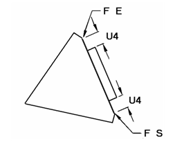
F and G lines define the starting point and the end point of a flange or face plate.
-
F S indicates that the first point to be defined is the starting point of a flange on the contour of the bracket.
-
F E indicates that the last defined point is the end point of the flange.
-
G S indicates that the first point to be defined is the starting point of a face plate on the contour of the bracket.
-
G E indicates that the last defined point is the end point of the face plate.
With the help of an additional numerical value, the starting point and/or end point of the flange or face plate can be shifted towards the end point or starting point.
Example:
F S U4
L AU6 U5 AV1 V2
F E U4
U4 specifies a displacement in relation to the starting point and the end point