Profile end types
Basic position of the profile end type
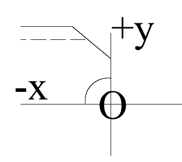
The type files stored in the profs, profs3d and profs2d directories in the norms describe the end type of a profile on one side (the right side of the profile). The type file describes the profile end shape in a two-dimensional plane. The system positions the end shape in the drawing, and processes it for the various production functions of CADMATIC Hull. The type files must be written from the perspective of a particular position. A profile end type shape must always be described in the second quadrant. To illustrate this, the correct positions are shown in the image below:
Optional variables for profile end types
Optional variables can be included in the profile end type files for:
-
Adjusting the end shape according to the profile properties.
-
Automatically applying extra length to profiles according to profile and end shape properties.
-
Automatically shortening profiles with straight end shapes in situations where the profile would not fit into the designed position because the profile has a slanted orientation to the related construction.
Adjusting the end shape according to profile properties
Variables (keywords) for some properties of profiles or face plates can be included in the type files of profile end types. Using these variables in the type file of an end type makes it possible to have the profile end shape calculated differently, and add cutouts or holes to it, depending on the profile properties. When the end shape adjusts to profile properties this way, one end type can be used for several situations, and less end types are needed.
It is possible to use variables that specify that the profile is a bent profile or a composite profile, and a variable that specifies the molded side placement of the profile or face plate. These variables represent the bent, composite and molded side placement properties of profiles and face plates.
The variables are as follows:
-
bent – Specifies whether the profile is bent or straight. Possible values:
-
0 – bent profile
-
-1 – straight profile
-
-
composite – Specifies whether the profile is a composite or a non-composite one. Possible values:
-
0 – non-composite profile
-
-1 – composite profile
-
-
msp – Defines the molded side placement of a profile or face plate. Possible values:
-
MSP_DEFAULT or 0 – molded side at the default position
-
MSP_BASEWIDTH or 10 – molded side on the thickness side
-
MSP_CENTER or 11 – molded side at the center of the profile of face plate body.
-
Additionally, it is possible to use a variable that specifies the position of the calculation plane of the face plate:
-
fpc – Defines the position of the calculation plane. Possible values:
-
FPC_DEFAULT or 0 – calculation plane is at the base line of face plate
-
FPC_CENTER or 1 – calculation plane is at the center of plate
-
Usage
These variables are used in the shape definition part of the type file, preceded by an IF statement. An ELSE can also be used.
In the following example, a different end shape is defined for composite and non-composite profiles:
IF COMPOSITE=0 : V4=H1*R1IV3+V2
ELSE V4=H1*R1IV3+V5
Applying automatic extra length to profiles based on the end type
It is possible to make the system automatically make profiles smaller of bigger based on the profile end type. This is similar to adding positive or negative extra length. It can be applied in the drawing, 3D presentation, DXF or sketch generation, and icon generation (any or all of these).
Automatic extra length can be enabled by defining in the end type files the profile and end type properties that work as conditions for adding the extra length, that is, defining in which situations extra length should be applied to a profile. Extra length is then automatically applied to profiles which match the profile and end type properties defined in the end type file.
For example, this way certain type of profiles within a certain size limit can be made bigger or smaller in the production information (profile sketch and DXF) but not in the drawing.
See Automatic extra length definition for profiles for more information.
Automatic shortening of profiles with straight end shapes
It is possible to automatically shorten profiles with straight end shapes in situations where the profile would not fit into the designed position because the profile has a slanted orientation to the related construction, and there is an overlap of related parts.
For this purpose, the values of the R1...R8 variables in the flange end type file can be used as variables R9...RG in the body end type file, and vice versa.
Variables R9...RG can be used in end type files to represent variables R1...R8, as follows.
-
When the end type is used for the profile body, the R9...RG variables represent the R1...R8 variables in the end type used for the profile flange.
-
When the end type is used for the profile flange, the R9...RG variables represent the R1...R8 variables in the end type used for the profile body.
Variable R9 gets the value of variable R1, RA gets the value of R2, and so on.
For an example of usage, see Example: Shorten flat bar profiles in help topic Automatic shortening of profiles.