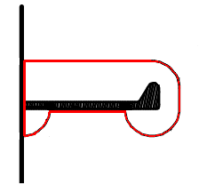
Shape definition
The shape of a profile end type, cutout, hole, corner hole or ridge is defined in the shape definition section of the type file.
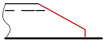
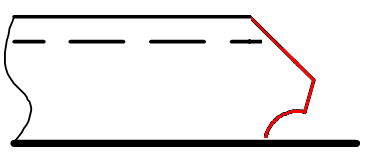
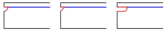
In the images below, a red lines indicate the shape of the type.
In the type file, the starting point and the order of the elements that define the shape is important.
-
The shape definition of profile end types always starts from the base line, and stops at the top line of the profile.
-
The shape definition of other types than profile end types is always done clockwise.
The shape definition begins in line 3 of the type file, and can extend up to line 62.
Elements of the shape
There are four shape elements that can be used in the shape definition:
- line segment (vector)
- point
- circle
- amplitude (scallop)
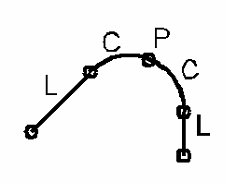
Each shape element type is defined in its own specific line, as described below.
All the shape elements are situated on a2D plane. A -x defines a direction to the left, and +x to the right. A-y defines a direction down, and +y up.
L line
A line segment is defined in a line starting with the letter L. This type of line defines the starting point and the end point of a line segment using the X and Y coordinates of the point.
A line segment starting at point (x0,y50) and ending at point (x2000,y100):
L 0 50 2000 100
Note: A zero-length line segment is removed from the contour. This is only valid if the line is not preceded or followed by a C line. This also means that such a line cannot influence an arc defined in an A line.
P line
A point is defined in a line starting with the letter P. This type of line defines one point using the X and Y coordinates. This shape definition item is only used as a start or end point of a arc if no line shape definition is present before or after the circle shape definition.
A point at (x0,y200):
P 0 200
C line
A circle is defined in a line starting with the letter C. This type of line defines a midpoint point (MP) using the X and Y coordinates, and a radius (negative for clockwise, positive for counterclockwise).
Note: A circle cannot be the first or the last line of the shape definition.
Circle midpoint at point (x100,y20) and a radius of 30:
C 100 20 30
Only a part of the circle's circumference is used, which results in an arc. The starting point and the end point of this arc must be defined using a preceding P or L statement.
In some cases the circle may followed by another circle. This is only allowed when the two circles have only one common intersection point. The intersection point will be the starting point and the end point of the two resulting arcs.
Note: The arc angle must always be below 180 degrees.
A line
It is possible to define scallop-type openings with A lines. The image below shows examples of possible openings created with A lines.
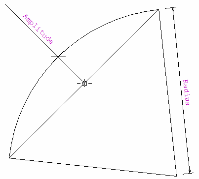
The first three values of an A line define the opening, and the last value defines the amplitude of the opening:
A <center x> <center y> <radius> <amplitude>
Exceptions:
-
If the last value of the line equals 0, the result is a straight line.
-
If the last value of the line equals to 1234567, the A-line behaves exactly the same as a C line
If the amplitude is negative, the center point is right to the line defined by the arc's starting and end points. If the amplitude is positive, it is at the left side. The amplitude can correct the center point and radius, but does not influence the arc's staringt and end points. The image below shows an example of the end result.
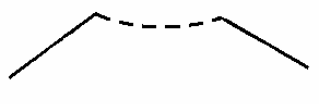
The end line of the shape definition needs to define a vector longer than 0, or it is removed from the shape contour.
Determining the starting or end point of an arc
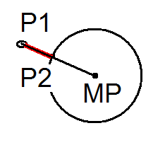
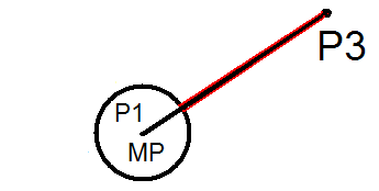
In some cases it is difficult to determine the exact starting or end point of an arc. The system can automatically correct the staring and end points of an arc. The system will correct the point, line, midpoint or radius depending of the situation and the given input. This happens only when the point is not exactly on the circle circumference. There are three main rules, as illustrated in the examples below.
-
The starting or end point is defined as P1. This point is corrected to be the nearest intersection point on the circumference of the circle between P1 and the midpoint MP of the circle, resulting in P2.
-
The starting or end point is defined as line P1–P3, and one of the points is equal to the midpoint of the circle. This point is corrected to be the nearest point on the circumference of the circle intersecting with line P1–P3.
-
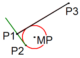
The starting or end point is defined as line P1–P3. The starting or end point of this line will be corrected to be the nearest tangent point on the circumference of the circle, resulting in P2.
Determining the midpoint of a circle
In some cases it is difficult to define the exact midpoint of the circle. The system can calculate the midpoint. There are four methods, as illustrated in the examples below.
-
Method 1:
C ? ? <var>
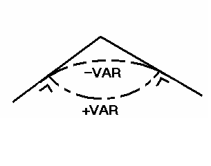
If the line before and after the circle are not parallel, and they have the same starting and end point, the midpoint is determined so that a rounding arc is drawn. The tangents of the rounding arc coincide in the points of contact.
-
Method 2:
C ! ! <var>
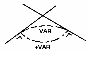
If the lines before and after the circle are not parallel, and they intersect with each other, the midpoint is determined so that a rounding arc is drawn. The tangents of the rounding arc coincide in the points of contact.
-
Method 3:
C # # <var>
In this case, the two lines do not have a common point, and the lines need not coincide with the tangent to the arc in the points of contact, or be at right angles to the tangents.
-
Method 4:
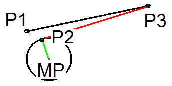
p 100 0
C ! ! -50
L 80 50 500 300
If C ! !<var> is used in combination with a point P2 and a line segment P1–P3, the radius and the midpoint will be changed. The radius will fit between the green and black line and the tangent to the black line P1–P3. It is important that the given radius is close to the real dimension. The clockwise or counter-clockwise direction must be defined by using the - or + sign. In this example, if the sign is positive, the midpoint will be on P1.