Status line
The first line or status line contains minimal two and maximal five pieces of information:
- The number of variables used;
- The maximum adjustment factor;
- The definition of the profile end types that determines which end type symbol should be used for the profile in bulb view (the so-called flag).
- The definition of the face plate end types that determines which end type symbol should be used for the face plate in side view (the so-called flag).
- The definition of the flange end types that determines which end type symbol should be used for the flange in side view (the so-called flag).
Note: The first and second arguments on the status line are obliged for all types. The third argument is only obliged for profile end type. The fourth and fifth arguments are optional.
Number of variables
This first argument that specifies the number of variables defined on the next line (variable content) should be at least 1. Therefore, at least one variable should be defined, even if this variable is not used.
Adjustment factor
The maximum adjustment factor determines the maximum value to be used to demarcate the absolute and the relative values in the shape definition. Positive numbers that are smaller than this value and negative numbers that are larger than -(this value) are automatically multiplied by the profile height. If a number falls outside this margin, it will remain the same and thus become absolute.
Note: The adjustment factor is mostly set to 0. This to control the shape definition by the user him self. This factor is only useful if the shape of the end type is totally depending of the profile height.
Profile end type flags
The third argument on the first line determines the profile end type flag.
The main purpose of the end flags is to indicate in section if the end type is connected to the related construction.
End type flags can also show what type of molded side placement the profile in section has.
Profiles use the following models to display molded side placement in end shapes:
- lb2/pr<x>.mod in case no molded side placement has been used
- lb2/prc<x>.mod in case the molded side placement has been set to Center
- lb2/prf<x>.mod in case the molded side placement has been set to Base width
lb2 refers to the models folder and in each model name, <x> stands for the number defined in the profile end type file. We provide in our default norms some examples, that is, molded side placement variations of pr0.mod, pr1.mod and pr2.mod.
When creating or editing an end flag model, it is important to indicate the attach point on the end flag. Attach points are used by Hull system to determine the correct thickness direction of profiles when they are dimensioned using the Chain tool.
The example below how to define the attach point on an end shape:
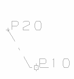
- While editing the end shape model, open the Command Window by selecting Hull > Help > Supporting Tools > Command Window.
- Move the cursor to the correct position at P20 at the end of the end flag line.
- Type in the Command Window: p20=c and press Enter.
- Define attach point P10 by typing in the Command Window: p10=p0.
- After defining attach points P10 and P20 at correct position the Hull model file can be exported. Export the model by selecting Hull > Export > Hull Model.
Face plate and flange end type flags
End flags at the ends of face plates and flanges on plates in plan view are shown automatically if the models are present and the model number is indicated by the fourth and fifth argument of the status line. The end flag can point to the outside of the plate, meaning that the face plate or flange is pointing towards the user. The end flag models have to be stored into the %NCGMODELLEN% directory.
Note: On face plates which have been defined as pipe, round or half round, the end flags never are shown automatically.
The fourth value indicates the face plate end flag, the fifth value the flange end flag. A negative value means 'no end flag'. If these values are omitted, then no end flags are shown. The number <x> for a face plate end flag indicates the model fp<x>.mod. The number <x> for a flange end flag indicates the model fl<x>.mod.
The end flags are presented by models which have to be stored into the %ncgmodellen% directory. The standard mod2d.ncg directory therefore contains the files fp0.mod, fp1.mod, fp2.mod and fp3.mod representing the face plate end flags and the files fl0.mod, fl2.mod and fl3.mod representing the flange end flags. The end type files type0, type2, type3 and type8 within the standard mod2d.ncg/profs directory shows the indication which face plate and flange end flags are shown. An example of such a line is: 4 0 0 3 3 indicating that the face plate end flag is fp3.mod and the flange end flag is fl3.mod.