Variables and constants (type files)
The second line in the type file contains the variables that are used in the shape definition. The system automatically assigns fixed names to these variables, from V1 up to VZ (V1...V9,VA...VZ).
Example:
-1 0.8 H1-R3 V3TR2 7 5
|
line content |
-1 |
0.8 |
H1-R3 |
V3TR2 |
7 |
5 |
|
variable name |
V1 |
V2 |
V3 |
V4 |
V5 |
V6 |
The number of variables must be equal the number specified in the type file's first line. If more variables than what is specified in the first line are defined in the second line, the system will not recognize the extra variables. The variables are used for two purposes:
-
For values that are regularly used in the shape definition.
-
To perform calculations with the database variables (R1...R8, H1, B1, A1...A4).
Note the following:
-
Lower case characters are not allowed in the variables. Always use upper case characters.
-
Variables that have not been defined yet must not be used in calculations.
-
Each variable declaration must be separated by a space.
V variables
Previously defined V variables can be assigned to variables. V variables can be used to write more compact lines of code or to perform calculations with other variables.
Fixed numerical values can also be used in calculations and combined with variables (for example, 4*10.5 and V4+114). See Operators for more information.
Real numbers can also be used instead of V variables, so it is not necessary to first assign a V variable to a value.

V variables (left) replaced with a fixed value (right) in a cutout type file
Additional variables
In addition to the variables defined in the type file, eight R variables R1...R8 can be defined for each type when creating an attribute (profile end shape, hole, cutout etc.). These variables are stored in the Hull database with a relation to the attribute. If they are not added to the database, they have a default value 0.
The height and width of the related item, profile or hole can also be used, by means of variables H1 and B1. If the related item is a profile (used by cutouts and/or end types) the H1 contains the profile body height, and B1 contains the profile thickness. In case of a hole (used by a ridge) the H1 contains the height of the hole and B1 contains the breadth of the hole.
There are some special variables (R1, A1...A4, R8 and R5...R8) with contain values given by the system. These variables can be used only in the proper environment. See below for more information.
Variables for profile end types
The R1 variable has a special purpose for profile end types. The contents of the R1 variable is the proportion in X direction of the end type shape in relation to the related construction.
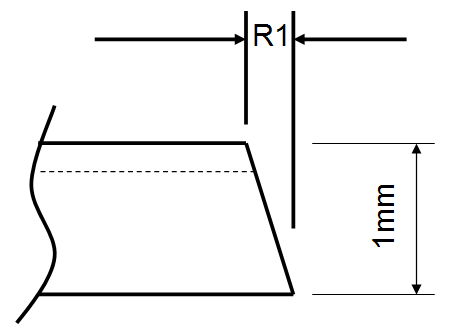
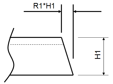
The contents of the R1 value is negative if the angle of the end type is smaller than 90 degrees.
Dimensions H1, B1, W1 and F1 have a meaning as shown in the image below. For profile types without a flange (flat bar, for example), W1 and F1 are set to the value of B1.
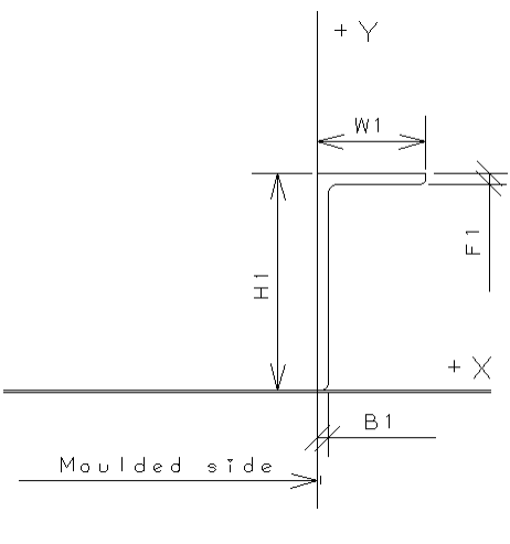
H1 – profile height
B1 – profile thickness
W1 – flange size
F1 – flange thickness
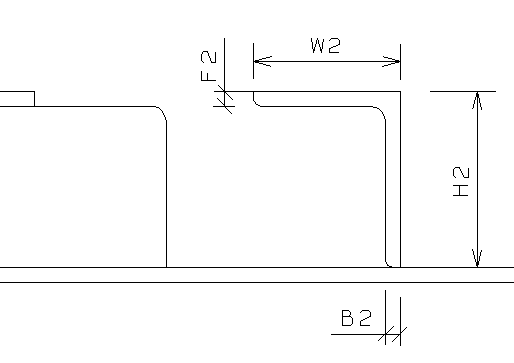
The dimensions of related parts can also be used when defining an end shape. These dimensions are H2 for height, B2 for thickness, W2 for flange size, and F2 for flange thickness, meaning height, thickness. The image below shows an example of these values. For profile types without a flange (flat bar, for example), W2 and F2 are set to the value of B2.
Extra length can added to an end type with the Green function. The value of this function can be used with the O variable.
Variables R9...RG
Variables R9...RG can be used in end type files to represent variables R1...R8, as follows.
-
When the end type is used for the profile body, the R9...RG variables represent the R1...R8 variables in the end type used for the profile flange.
-
When the end type is used for the profile flange, the R9...RG variables represent the R1...R8 variables in the end type used for the profile body.
Variable R9 gets the value of variable R1, RA gets the value of R2, and so on.
For an example of usage, see Example: Shorten flat bar profiles in help topic Automatic shortening of profiles.
Bevel dimension variables
Bevel dimension parameters for the bevel angle (A), bevel height (H) and nose (N) can be used as variables in B lines in profile end type files to output the bevel dimensions to profile robot files. L and U are used to determine whether the angle or height is the lower or upper angle or height. The parameters are as follows:
-
UA — upper bevel angle
-
UH — upper bevel height
-
NH — nose height
-
LA — lower bevel angle
-
LH — lower bevel height
Example
BB7* TY K B1UA UA B2UH UH+V7 B3NH NH B4LH LH B5LA LA
Note that these parameters work for predefined bevels only.
Additional variables
The following additional variables can be used in the end type files. The values can be given either as a constant or an integer form.
-
CC – Construction code. Specifies the type of part.
 Show/hide possible values
Constant Integer Meaning C_CODE_SHELLFRAME 2 shell frame C_CODE_PROFILE 400 profile C_CODE_PILLAR -400 pillar C_CODE_BENT_FACEPLATE 452 bent faceplate C_CODE_FACEPLATE 453 straight faceplate C_CODE_SHFTD_BENT_FACEPLATE 454 non-centered bent faceplate C_CODE_SHFTD_FACEPLATE 455 non-centered straight faceplate C_CODE_BENT_PROFILE 456 bent profile C_CODE_BENT_PILLAR -456 bent pillar -
CT – Construction type. For profiles this is the profile type number. For example, 400 for flatbars, and 401 for bulb profiles.
-
CE – Position of the endcut (either body or flange).
Show/hide possible values
Constant Integer Meaning EC_BODY 0 body EC_BODY_1 0 1st body EC_BODY_2 1 2nd body EC_FLANGE 2 flange EC_FL_TOP 2 1st flange EC_FL_BOT 3 2nd flange -
ECB – Type number of the endcut used in the profile body.
-
ECU – Type number of the top first (top) flange.
-
ECL – Type number of the 2nd (bottom) endcut.
-
XL – The amount of extra length (same as variable 01).
-
BL – Base length of the profile as stored in the logistical database. In case this value is not available (yet), it is the distance between start point and end point of the profile.
-
PT – Process type. For use with conditional expressions. Specifies the process in which the condition is to be applied. The values define the process. For example, when defining automatic extra length for profiles, this variable can be used to define that the extra length is only applied in a specific process.Show/hide possible values
Constant Integer Meaning PT_UNKNOWN 0 unknown process PT_DRAWING 1 drawing generation PT_3DMODEL 2 3D model generation PT_DXF 3 DXF generation (coding) PT_SKETCH 4 Sketch generation PT_ICON 5 Icon generation
Below are some examples of the usage of the additional variables. More examples can be found in the profile end type files in the default norms.
Example 1
Set the value of variable VA to 0 for 3D model generation.
IF PT=PT_3DMODEL: VA=0
Same using an integer instead of a constant:
IF PT=2: VA=0
Example 2
Set the value of variable VC to 10 if the process type is other than Drawing and if the base length of the profile is smaller than 1000, otherwise set it to 0.
IF PT<>PT_DRAWING & BL<1000: C=10
ELSE VC=0
Example 3
Set the value of variable V6 to be dependent of the type of the part, and use 0 if the part type is not any of the defined ones.
LET V6=0
IF CC=C_CODE_FACEPLATE: V6=10
IF CC=C_CODE_BENT_FACEPLATE: V6=20
IF CC=C_CODE_SHFTD_FACEPLATE: V6=30
IF CC=C_CODE_SHFTD_BENT_FACEPLATE: V6=40
Variables for cutouts
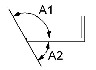
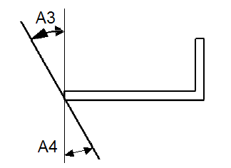
The A1, A2, A3 and A4 variables can be used for cutouts. They define the angles of the intersection between the cutout and the base plane, as shown in the image below.
Variables for lugs
The A1, A2, A3 and A4 variables can be used for lugs. They define the angles of the intersection between the lug and the base plane.
In addition, the R1...R8, H, B, W and F variables from the related cutout type file can be used in the lug type files. To avoid interference with the R1...R8 variables used in the cutout type files, lug type files should use variables R9, RA...RG.
Constants for lugs and cutouts:
The following constants are available for lugs and cutouts:
- TB – Contains the body thickness of the profile or the shell frame passing through the cutout.
- TF – Contains the thickness of the flange of a shell frame or profile passing through the cutout. If the profile type has no flange then TF is zero.
- TH – Contains the thickness of the plate, the profile or the shell frame which contains the cutout.
These thicknesses are used to define the plate, profile or shell frame without any compensation for slanted crossing parts.
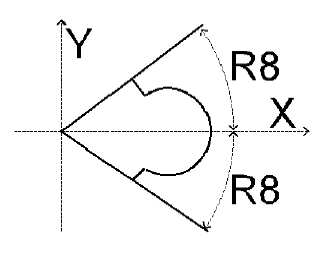
Variables for corner holes
A special orientation is used for corner holes and extended corner holes.
The R8 variable gets automatically the value of a half angle. This angle is helpful when defining the boundary of the corner hole or hole.
If the type is especially made for this purpose it is necessary to add the dv_position=2 variable definition in the type[number].cmd type macro after label 3. See Type macro for more information.
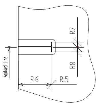
Variables for girder cutouts
The system defines variables R5, R6, R7 and R8 automatically. These variables are helpful when defining the girder cutout.