Hull boundary lines
Hull boundary lines are hull lines that are derived from the hull shape. Boundary lines are extracted from hull groups, and they are the outer edges of the hull groups. Adjacent hull groups both have a boundary line at the intersection of the hull groups.
Hull boundary lines are dimension lines like user-defined dimension lines, and they can be used as relations when creating shell plates by defining the relations manually with the Shell Plates by Relations function. The system cannot use hull boundary lines when defining the shell plate relations automatically in the Enclosed Shell Plate function.
Hull boundary lines are imported and exported with the Import Block and Export Block functions.
Limitations
-
Hull boundary lines are read-only, and cannot be created, modified or deleted in the Shell application.
-
Hull boundary lines are not topological.
-
Defining and assigning hull line ranges and subsets does not apply to hull boundary lines.
Extracting hull boundary lines
Hull boundary lines are extracted from hull groups and saved into the hull database in the following situations:
-
When a new project is created.
-
When the currently used hull shape database is updated. This can be done in System Management > Projects > Update Hull Database.
-
When a new hull shape database is activated. This can be done in System Management > Projects > Activate Database.
Extracting and saving hull boundary lines is optional. The system will show a dialog where you can select whether to update the hull database with hull boundary lines and/or hull group intersection lines.
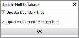
If you do not need these hull lines or do not want to update them, clear one or both of the check boxes. Click OK.
Viewing hull boundary lines
Hull boundary lines can be viewed in shell views like other types of hull lines. Because hull boundary lines are created as dimension lines they may not always be visible in shell views.
To make hull boundary lines visible, use the Show Hull Lines function. Select the second Dimension lines option in the dialog, and set the range of boundary lines to show.
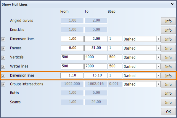
The range is defined as hull line numbers. Hull boundary line numbering starts from 1.1. Decimal .1 indicates that the line is a boundary line. Subsequent lines are numbered using an increment of 1 (1.1, 2.1, 3.1, ...).
Hull boundary lines in the COS environment
Boundary lines are part of the Hull shape object, and not part of any subset of hull line ranges. All operations on the Hull shape object in the Check Out/In dialog apply to both the hull shape itself and also to the hull boundary lines.
If you want to share the hull boundary line data with other sites, you must save the Hull shape object to COS.
In the COS environment the boundary hull lines are saved as an attachment with name boundary_lines.hca. This zip file contains a directory for each boundary hull line. The format and content of the directory is the same as the format and content of the hull line directories found in the Hull project itself. For example: gr0_DS_1.1.