Production property
The production property determines the function of a hull line in the production process.
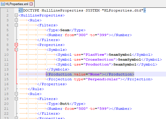
The production property can have the following values:
- Mark – The system adds the line as a marking line. The line will be placed on the marking layer.
- Cut – The system adds the line as a cutting line. Cutting lines are placed on the cutting layer just like holes, since both are relevant for the cutting process.
- Paint – The system adds the line as a paint line. Paint lines mark the limits of the painted part of the shell plate. Paint lines are placed on the marking layer.
- SideLine – The system adds the line as a side line. Side lines are placed on the marking layer.
- BaseLine – The system adds the line as a base line. Base lines are placed on the marking layer.
- None – The hull line will not appear on the shell plate, it's filtered out by the system.
Specifying the location of base line and side line symbols
The system manager can create extra markings on the end of the hull lines for side lines and base lines. These markings appear at specified distances from the edges of the projected hull line, as long as the line is longer than the predefined threshold. If the hull line is shorter than the threshold, a single symbol is used around the center of the line.
The system manager must create the SideLine1.mod, SideLine2.mod and BaseLine1.mod, BaseLine2.mod models to define where on the hull lines the system should place the side line and base line symbols should be placed. The numbers in the file names indicate whether the symbol is intended for the starting edge (1) or the ending edge (2). If these files are not found in the %ncgmodellen% directory, the system skips the symbol in the output. The models must be placed in the project's norm folder, mod2d subfolder.
The settings that define the distances of these symbols from the starting and ending edge of the hull line are defined in the cam.conf file in the project's norms folder. The following settings are used:
- slplnposoffset – Determines the distance from the edge of the line, where the symbol needs to be placed.
- slplnposthreshold – Determines the minimum line length needed to trigger the system to mark both ends
The symbols follow the hull line's orientation. This means that the horizontal axis of the symbol is aligned to the tangent of the hull line at the placement point. In case the projection of the hull line resulted in multiple branches, every one of these branches will become an extra symbols.
Paint line distances
Paint lines can be used to indicate the paint line on the shell of the real ship. The painter can use these lines to determine how to paint different plates before the assembly of the ship.
Note: Paint lines are always projected on the outside of the shell plates. The projection direction used is the current view’s depth direction. This means that slightly different results can be obtained by using the function on the same shell plate in different views, if the plate is sufficiently twisted along the depth axis in the new view. The resulting distances are formatted using zero (0) decimal points in either metric or imperial systems, depending on the general project settings. The image below illustrates how the projection of paint lines can be affected by the view.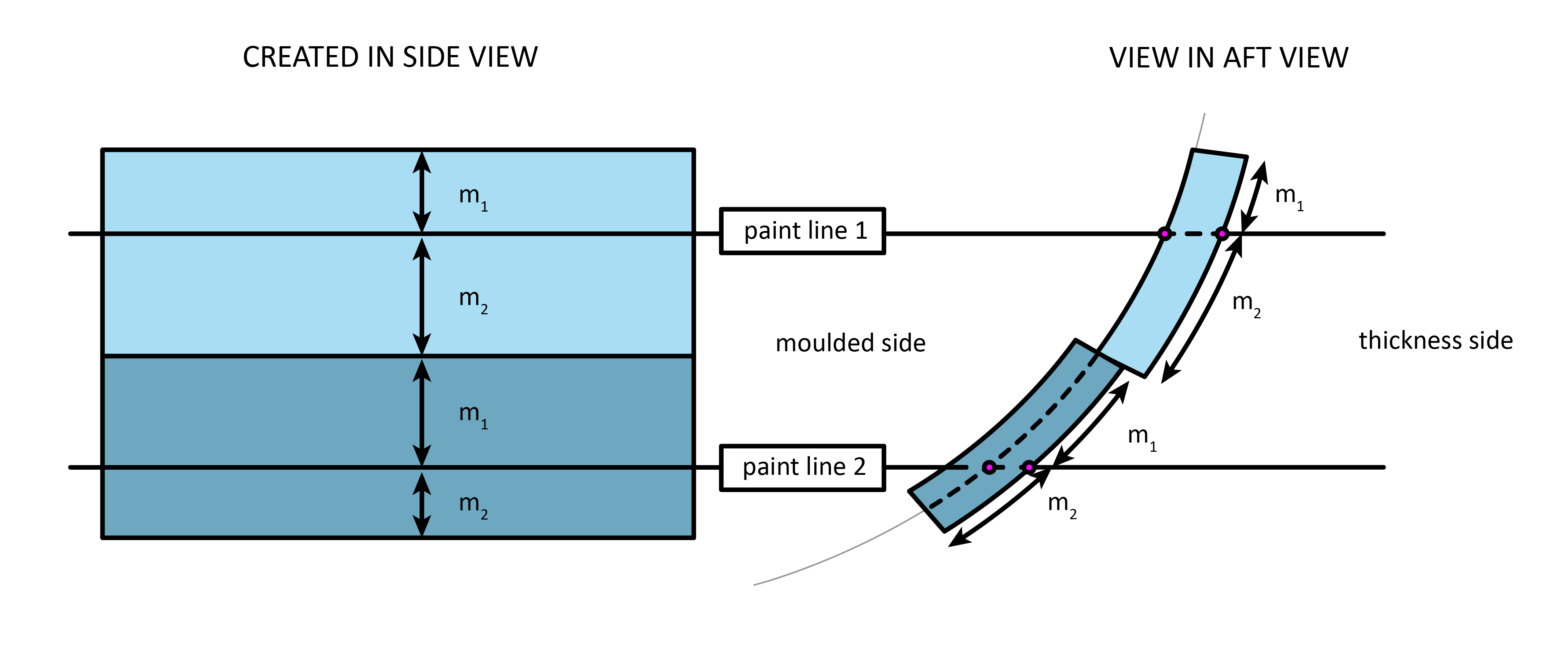
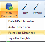
You can display the distance between paint lines and the shell plate contour by selecting Draw > More Dimension > Paint Line Distances in the Shell application.
The distance is added in the form of dimensions.
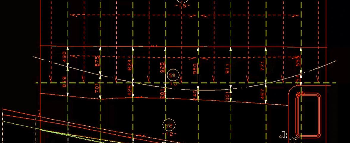
- The distances are displayed as rounded numbers without decimals (in the metric system) or a fraction (in the imperial system).
- This function can be used in aft, side and top views.
- The dimension is a normal 2D-item and can be changed using the 2D-properties function.
- If a shell plate contour and/or paint line is changed, the distance can be refreshed by removing the dimensions and then doing the Paint Lines Distances function again.