Direction types
The direction is specified for all points and the overall angle is computed and displayed in the point list. If the direction evaluation fails, an automatic direction is selected. This automatic direction has angle 0 with baseline, and the value for the directions in the points list is 'error'.
Direction types
The list below describes all the available direction types.
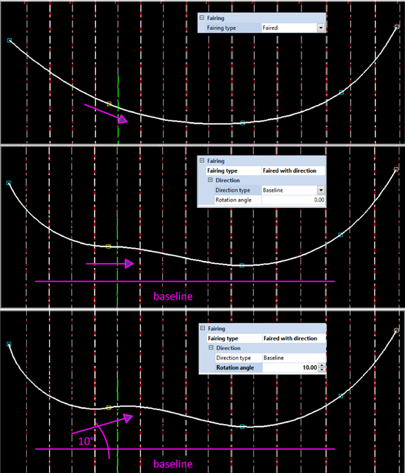
Baseline
When selecting Baseline as direction type, the direction of the point on the hull line aligns with the baseline direction.
The rotation angle is the angle between the tangent to the 2D curve at the selected point (incoming and/ or outgoing directions) and the baseline. The angle is measured counter clockwise from the baseline to the outgoing/ incoming direction at the selected point. The angle is view dependent.
The image below shows an example, where the direction of the second point of the hull line is changed from Faired to Faired with direction to baseline with 10° rotation angle.
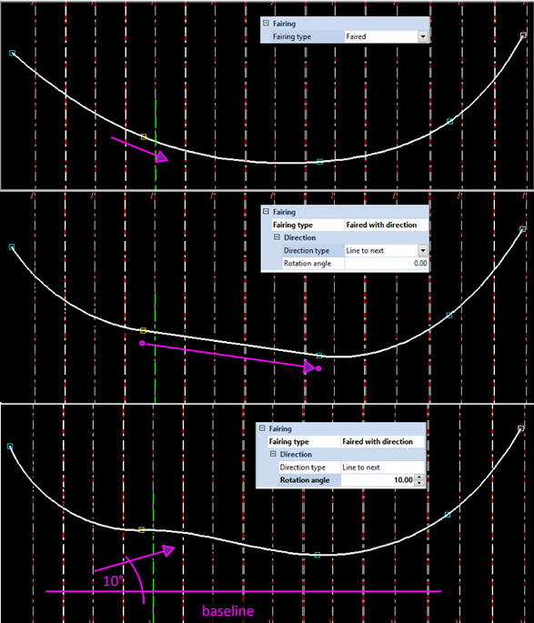
Line to next
When selecting Line to next as direction type, the direction of the curve (incoming and/or outgoing) at the selected point will point to the next hull line point. This direction is view independent. An additional rotation angle can be specified. This angle is measured counter clockwise from the base direction and is view dependent.
When the additional rotation angle is 0 and the incoming direction at the next point is not specified explicitly, the resulting segment in the hull line is straight.
The image below shows an example, where the direction of the second point of the hull line is changed from Faired to Faired with direction to the next hull line point with 10° rotation angle.
Topological Direction Types
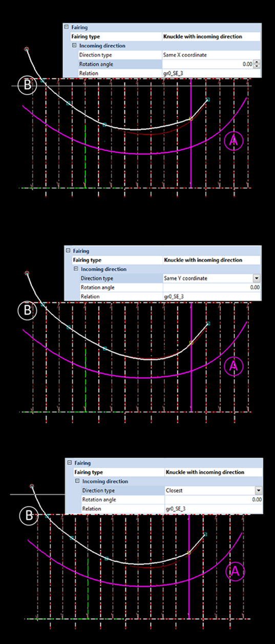
When you define curve directions based on hull line relations, the result will be a topological direction. In case a curved hull line 'A' is used as a relation to define a point in hull line 'B', the curve directions of hull line 'A' can be used to define the fairing of hull line 'B'. (See image below this section.)
The following directions types are topological:
Same X coordinate
When selecting the Same X coordinate direction type, the system searches the closest point with the same X coordinate on the selected relation. This is done with respect to the coordinate axes of the view. When the system finds a point that has the same X coordinate, the curve direction through the selected point will be equal to the curve direction through the point found on the relation.
If no point is found, the direction evaluation fails and the hull line cannot be created. In cases where more than one point is found, the point on the relation that is closest to the position of the hull line point is used.
You can specify an additional rotation angle. This angle, measured counter clockwise from the baseline direction, is added to the evaluated value. As the baseline direction changes with the view, the value of the additional rotation angle is view dependent.
Same Y coordinate
Behaves similar to the Same X coordinate direction type, with the difference that in this case the system searches the closest point with the same Y coordinate on the selected relation. An additional rotation angle can also be specified.
Closest
This direction type behaves similar to the Same X coordinate direction, with the difference that in this case the system searches the point closest to the position of the current hull line point. The distances are taken with respect to the current view. An additional rotation angle can also be specified.
Intersection Planes (In-plane Bending)
You can also define in-plane bending with the existing fairing specification. An intersection plane is formed between two consecutive fairing points and one additional point. The image below shows three intersecting planes on a hull line faired through four points.
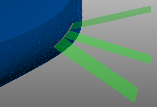
The position of the additional point in 3D space determines how the plane intersects with the hull. This influences the fairing of the hull line segment between the two other points. It also results in an angle between plane and hull.
This method is used to place potential shell frames in line with an intersection plane by means of a topological relation with the relevant hull line segment.
The angle of the intersection plane is the angle of the shell frame and is user-defined in various ways. It can be set for each point in the hull line with the following direction types:
The intersection surface is constructed differently for each fairing type. The behavior is the following:
- When defined for the incoming direction: the plane formed between the current point, the previous point and it's the angle is the intersection plane
- When defined for the outgoing direction: the plane formed between the current point, the next point and it's angle is the intersection plane.
In the 2D graphical window, the intersection plane between the two involved points is presented by a straight dashed line instead of the evaluated faired line.
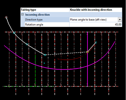
The hull line in the image below is faired through six points. The fifth point has been defined with the fairing type Knuckle with incoming direction. The direction type is angle to base in aft view. As a result, the line segments between the involved points are presented as follows:
Note: Using the wrong combinations will lead to a conflict. One can not define the second point with the fairing type Knuckle with outgoing direction and the third point with the fairing type Knuckle with incoming direction, as both fairing types will want to influence the same line segment. In such situations the text 'conflict' is shown in the points list for the selected directions.
The angle of the in-plane bending can be set in several different ways:
Plane: angle to base (aft view)
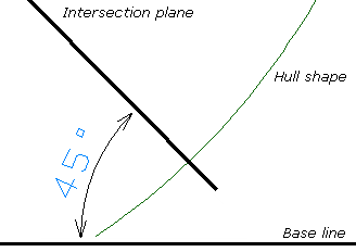
The angle has a default value of 45 degrees and can be manually adjusted. It is measured against the rotation angle of the base line, from the viewing perspective of an orthogonal aft view.

|
|
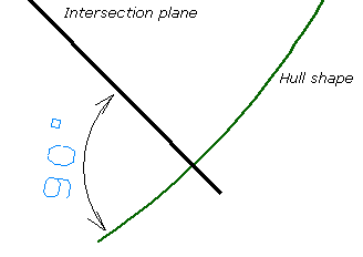
Plane: angle to shape (aft view)
The angle has a default value of 90 degrees and can be manually adjusted. It is measured against the rotation angle of the hull shape at the current point, from the viewing perspective of an orthogonal aft view.
|
|
Plane: angle to base (perpendicular)
The angle has a default value of 45 degrees and can be manually adjusted. It is measured against the rotation angle of the base line. The viewing perspective is perpendicular to the hull shape at the current point as seen from a top view.
Plane: perpendicular to shape
The angle is determined automatically, by measuring perpendicular to the rotation angle of the hull shape at the current point, in all directions.
Note: When an intersection plane is defined at a point, it influences other fairing properties defined at the neighbouring point involved in the plane definition. Fairing specifications of the type Faired and Faired with direction will be treated as Knuckle and Knuckle with direction. Rounded corners will not be considered for the dashed line segment.