Jig planes, jig views, and jig pillars
You can create indication for the position and height of jig pillars in the Shell application in perpendicular views, aft views, side views, and top views.
First you must create jig planes for shell plates, then create the jig views, and finally add jig pillar heights to the jig views.
Creating jig planes for shell plates
Do the following:
-
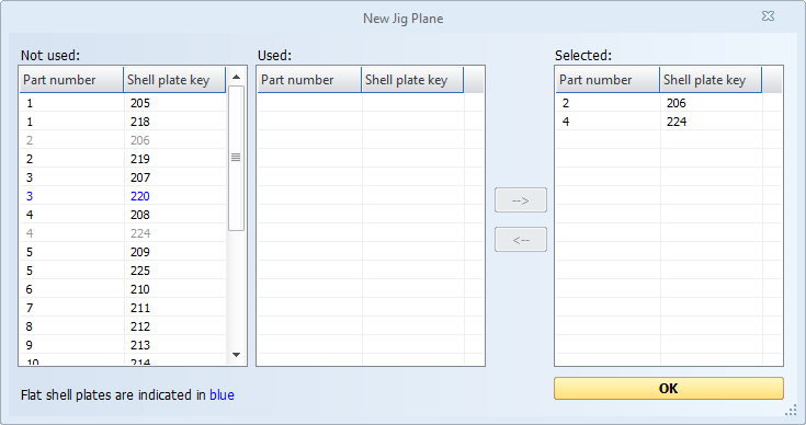
Select Template > Jig Plane. The New Jig Plane dialog opens.
-
Select the desired shell plates and move them to the Selected list with the arrow right button.
-
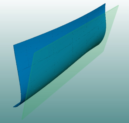
Click OK to confirm your choice. The system automatically calculates the optimal jig plane for the shell plate(s). When creating jig views later, only the relevant shell plates are visible in the jig view.
Creating jig views
Do the following:
-
Select Home > Create Perpendicular, Create Aft, Create Side or Create Top, depending on the view you need.
-
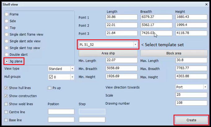
Select Jig Plane in the top left corner of the Shell view dialog. The system automatically reads all the jig planes in the current block.
Note: The Jig Plane option is available only if have license for the Pin-Jigs module, and if you created jig planes previously. In case the system cannot find predefined jig planes, the option will not be available.
-
Make sure the template set is selected in the drop-down menu.
-
Click Create to create the jig view. The jig view appears in the graphical window.
Adding jig pillar heights to jig view
Do the following:
-
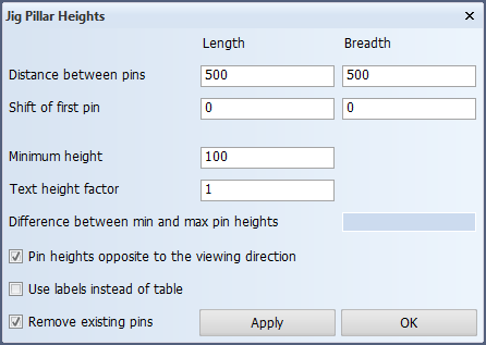
Select Draw > More Dimension > Jig Pillar Heights. The Jig Pillar Heights dialog opens.
-
Define the following settings:
-
Distance between pins – Distances between the individual pins of the jig. You can specify pin distances both along the length and breadth of the jig. The values must be bigger than 0. The default value for both fields is 500 mm.
-
Shift of first pin – Offset for the first pin of the jig along the length and the breadth. With this settings you can offset the entire jig to a location within the shell plate(s). The default value is 0 mm.
-
Minimum height – Height of the lowest pin in the jig. This ensures that the jig pillars are calculated in such a way that the lowest height of a jig pillar is the specified value. This value must be bigger than 0. The default value is 100 mm.
-
Text height factor – Text height on the jig drawing. The factor is calculated by dividing the Text Scale Default setting for Plate Cutting Data by 25 (the default for the setting). The text height factor must be bigger than 0. The default factor is 1.
-
Difference between min and max pin heights – Display the calculated difference in mm between the min and max pin heights according to the current settings. Click Apply to calculate the value.
-
Pin heights opposite to viewing direction – Reverse the jig plane (jig floor) position.
By default the system positions the jig plane at the viewing side:
-
Jig plane at top when view direction is toward bottom
-
Jig plane at bottom when view direction is toward top
Selecting this option reverses the jig plane position:
-
Jig plane at top when view direction is toward top
-
Jig plane at bottom when view direction is toward bottom
-
-
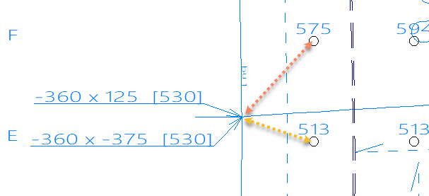
Use labels instead of table – Use labels instead of a table for showing the pin jig measurement values in the jig view. The labels are placed near the shell plate corner and contain the horizontal and vertical distance of the nearest pin to the shell plate corner, and the pin's height. An arrow points to the first pin that is connected to the shell plate.
-
Remove existing pin jigs – Select this if existing pins in the drawing should be removed before new ones are placed.
-
-
Click Apply to preview your values, or click OK to add the pin jigs.
Note: Clicking Apply triggers the calculation of values based on the user input added in the dialog. It updates the shell view and updates the values in the Difference between min and max pin heights field. The system saves the choices that have been used the previous time of creating jig pillar heights and will use them by default again when the user starts the function in the same project.