2D Drafting Exercises
- Indicating 2D Items
- Draw Lines, Circles and Duplicate Selection
- Modify Corners, Lines and Circles
- Draw Multiple Parallel Lines
- Draw / Modify Rectangles
- Mirror / Move Selection
The following exercise involves several of the 2D drafting functionalities in CADMATIC Hull. This exercise has nothing to do with the engine room block you are creating, but instead it is an additional exercise meant to make you familiar with the commonly used 2D drafting options.
Overview of actions:
- Indicating 2D Items
- Draw Lines, Circles and Duplicate Selection
- Modify Corners, Lines and Circles
- Draw Multiple Parallel Lines
- Draw / Modify Rectangles
- Mirror / Move Selection
- Save the drawing with the name 'truck'
Indicating 2D Items
Concerning 2D items the first thing you start with are the different ways in which they can be selected. A 2D item can be indicated in three ways:
- Indicating/selecting one item by cross-hair selection.
You can select one item by a left mouse button click on the item. This is called the cross-hair selection. By pointing to the item you want to select and pressing the <Space> key the pointed item will be selected.
- Selecting one or more items by clump/conflict selection.
For selecting one or multiple items, drag a clump or a conflict box by pressing the left mouse button and moving the mouse while the mouse button is pressed.
- Include/exclude items from selection group.
For including or excluding items from selection group use the cross-hair, clump or conflict selection in combination with the <Shift> key.
- Clump Selection Box
Dragging a box (with the left mouse button pressed) from left to right will select items which lie fully inside the box.
- dragging clumping box

- after clump selection

- Conflict Selection Box
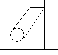
Dragging a box (with the left mouse button pressed) from right to left will select items which lie fully or partly inside the box. In the pictures below you see how to select the line and the circle by dragging a conflict box.
- dragging conflict box

- after conflict selection

- Using <Shift> key
|
Cross Hair + <Shift> |
|
|
Clump Box + <Shift> |
|
|
Conflict Box + <Shift> |
|
Draw Lines, Circles and Duplicate Selection
In this exercise the following functions are described:
Latching; Draw Circles; Draw Line Segments; Duplicate selection; Draw Parallel Lines;
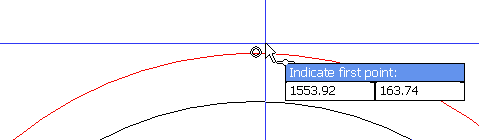
Before you begin, open the tab View and activate the Latching to enable the 'Latching' system. This will aid you when snapping to points of significance, such as endpoints, midpoints, intersection points, perpendicular points, tangent points, etc. When 'Latching' is enabled, an icon near your mouse arrow will appear indicating the type of point you can snap to. The icon changes as you move your mouse around areas with multiple snap possibilities. Example of a midpoint snapping icon:
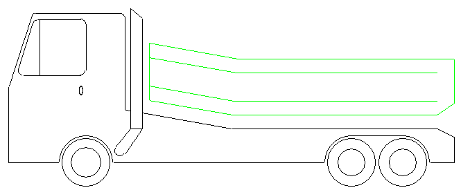
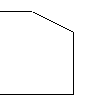
In this exercise, you will draw a basic truck. The basic truck contains the most commonly used elements of the 2D drafting functionality in CADMATIC Hull.
Please click the icon Blank Drawing in the Drawing section of the Home tab to start with a clear screen. Let's begin by selecting the Draw tab:
Click the arrow under icon Circles in the Draw section and choose Centre, Radius:
![]()
![]()
Alternatively, you can also directly click on the icon Circles, which starts the first function in the list.
In order to enter a value into the dynamic input field, you press the <Tab> key. Make sure that while typing you do not move the mouse, or else you will lose the focus. After you have specified the first value, press <Tab> again to enter the second field.
Enter the coordinates to position the circle: 0, 0. Press <Enter> to confirm your input.
Enter the radius of the circle: 100. Exit the function by pressing the <Esc> key.
The circle is now automatically selected. Duplicate the circle by pressing hotkey <d> and specify the distance and angle: 1850, 0.
Start the Line Segments function:
![]()
Press the <Tab> key again to place the cursor inside the dynamic input field, and enter the coordinates given below. When the endpoint of a line ends up outside of your view area, you can use the standard zoom and pan functions without exiting the Line Segments function.
Enter the starting coordinates: -450, 0;
Enter distance and angle: 2600, 0;
Enter distance and angle: 200, 90.
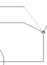
Press hot key <t> to activate the 'temporary line' function and use hot key <m> to snap to the midpoint of the lower horizontal line
Enter distance and angle: 200, 90;
Enter distance and angle: 600, 170;
Enter distance and angle: 600, 90;
Enter distance and angle: 90, 320.
Now draw a straight vertical line by using hotkey <p> to snap perpendicular to the lower horizontal line. You can also use the latching icon for perpendicular lines.
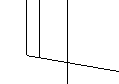
Proceed to click the icon Parallel Lines:
![]()
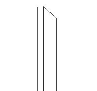
Of the two vertical lines, indicate the left one and use a parallel distance of 30 on the left side of it, and the result should be like this:
Start the Line Segments function:
![]()
Enter the starting coordinates: -450, 0;
Enter distance and angle: 450, 90;
Enter distance and angle: 450, 72.
Use hot key <p> to snap perpendicular to the vertical line that you created with the Parallel Lines function.
Modify Corners, Lines and Circles
In this exercise the following functions are described:
Fillet; Chamfer; Extend; Gap in Line; Draw Circle; Draw Line Segments; Trim.
Click the icon Fillet in the Modify section:
![]()
For the two upper corners of the cabin, use a radius of 20. For each one click both lines that make up the corner and then enter the value for the radius.
Click the icon Chamfer to snipe the upper corner on the back end of the truck:
![]()
Proceed to click the horizontal line first, followed by the vertical line. Use a distance of 100, followed by a distance of 50. The first value you specify will always pertain to the first line you have indicated.
Now use the Fillet function to extend the line behind the exhaust pipe to the back line of the cabin. Enter a radius of 0 to create a closed corner.
Click the icon Extend to extend the left line of the pipe to the bottom line of the truck as well:
![]()
First you have to indicate the line you want to extend to. Proceed by pressing <Enter>. Now you can indicate the line to be extended.
Click the icon Gap in Line:
![]()
Place the gap by using the latching system to snap to the points where the pipe intersects with the truck. Make sure that the intersection icon appears:

Also make sure that the line in which you want to place the gap, lights up before you indicate the intersection point:
Create a new circle by clicking the arrow under icon Circles in the Draw section and choose 2 Points:
![]()
![]()
Place this circle exactly in between the two lines of the pipe. For the first point you can click anywhere on one of the vertical lines of the pipe. For the second point, use the hotkey <p> to snap perpendicular to the other line of the pipe.
Exit the function by pressing <Esc> and proceed to select the newly created circle.
Now move the circle using hot key <s>. Instead of a length and angle, you will enter a set of coordinates to specify the new position of the circle. In order to do this, you will first have to activate the dynamic input field for coordinates by toggling the FDO option '8'.
FDO stands for Function Dependent Option and appears at the top of the graphical screen the moment you start a function.

Click with the mouse on the FDO 8 = Value. The text changes to 8 = Coordinates. Click for a second time to activate the input field for coordinates.
Enter coordinates: 200, 70. The circle should now appear to the left of the pipe:
Start the Line Segments function:
![]()
Place the first point of the line segment at the following coordinates: 260, 200.
In order to determine the second point, move the mouse near the upper side of the circle to the left of the pipe and click the right mouse button. In the menu that appears select Snaps > Tangent. For future use you can also press hot key <j>.
Exit the function with hot key <Esc>.
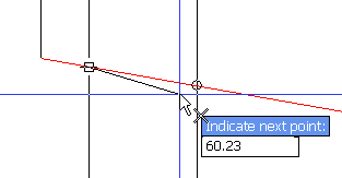
Start the Line Segments function again. Proceed snap to the start point of the newly drawn line by using hot key <i>, and draw a horizontal line from there straight across the pipe. Snap to the other vertical line with hot key <p>.
While still in the Line Segments function, snap to the circle again with tangent hot key <j>. The drawing should now look like this:
Click the icon Trim in the Modify section to trim all the excessive lines:
![]()
First you indicate the line you want to trim from, which in this case is the short horizontal line that runs across the pipe. After confirming with hot key <Enter>, you click the two lines of the pipe at the bottom ends.
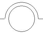
Start the function Gap in Line again to create a 50% gap in the circle.
![]()
The first point you indicate will determine which side of the circle will be cut. The direction in which the cutting will take place is always counter-clockwise. Use hot key <i> to indicate the upper left intersection point first, followed by the lower right intersection point.
You will see that the wrong side of the circle is now cut. You can quickly change this by pressing hot key <6> to invert the arc.

Draw Multiple Parallel Lines
In this exercise the following functions are described:
Draw Parallel Lines; Fillet; Trim and Extend lines; Draw Line Segment with Temporary Line; Delete line.
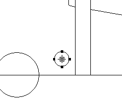
Draw a second circle around the wheels by using the Parallel Lines function in the Draw section:
![]()
Indicate one of the wheels and move the mouse pointer to the outside of the wheel. The system remembers the last used value for this function. Please use the parallel distance of 30 for both wheels and confirm with <Enter>.
Note: In the event that the value of 30 is already present in the input field, pressing <Enter> without first activating the input field will immediately draw the parallel line with the 30 as its distance.
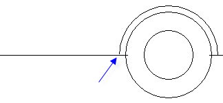
Proceed to use the Trim and Gap in Line functions to finish the wheel as shown in the following detail and then repeat the process for the other wheel:
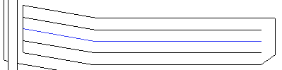
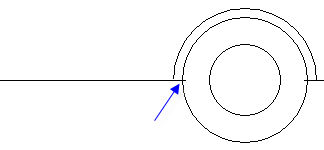
Use the Parallel Lines function to create the following situation:
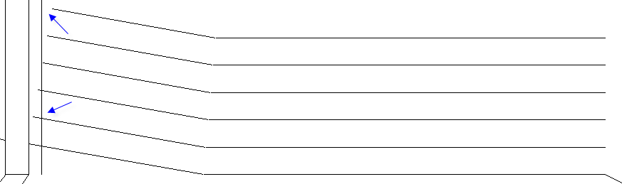
The distance is 82 and the number of lines is 5. Repeat the Parallel Lines action on the right line of the pipe with distance 40 and number of lines 1. Now use the Fillet function with a radius of 0 for the intersection points of the new lines, as well as the corners indicated in the detail by the blue arrows.
Now trim and extend the parallel lines to the new vertical line next to the pipe. When using the Trim function, it is also possible to extend lines by pressing and holding the <Shift> key while selecting the lines to be extended.
Now draw a new line at the back end of the truck, starting at the position indicated by the blue arrow in the detail to the left:
|
|
|
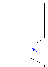
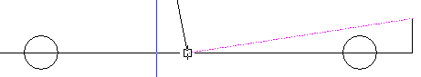
Use hot key <t> to draw a temporary line towards the back of the truck and use hotkey <e> to set that point, as shown in the detail to the right.
Enter distance and angle: 200, 90;
Enter distance and angle: 500, 90.
Now start up the Fillet function for the corner. The position on the lines where you click with the fillet function determines how the lines are trimmed. Click the horizontal line first, proceeded by the upper part of the vertical line. As you can see, the wrong side of the vertical line is trimmed.
Press the hot key combination <Ctrl> + <Z> to undo the fillet action. Repeat the fillet function and this time click the lower part of the vertical line.
Proceed to select the two lines indicated in blue by pressing and holding the <Shift> key while clicking them respectively.
Press the <Del> key to delete them simultaneously.
Draw / Modify Rectangles
In this exercise the following functions are described:
Draw Rectangle; Split up Rectangle; Apply Corner Radius; Draw Parallel Lines; Draw Ellipse.
Now you will create the window. Click the Rectangle icon in the Draw section:
![]()
Enter the starting coordinates for the first corner: 0, 840;
Enter the distance values for the second corner: -270, -330.
Upon creating a rectangle, hot key <6> will start the FDO "Corner Radius [0]" which makes it possible to specify a corner radius to be used when drawing the rectangle. In this exercise you will add the corner radius after you have drawn the rectangle.
Exit the function with hot key <Esc>.
In order to place a corner radius on a rectangle, you must first split the rectangle into four separate lines. Right click the rectangle and choose Manipulate > Split.
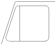
Now create a line parallel to the windshield with a parallel distance of 20.
Proceed to apply the corner radius of 30 on the rectangle and the parallel line, using Fillet, as shown:
Create an ellipse by clicking the arrow under icon Ellipse in the Draw section and choose Axis, Radius:
![]()
![]()
Enter the starting coordinates of the first axis: -30, 450;
Enter distance and angle of the first axis: 50, -90;
Enter radius of second axis: 10.
Exit the function with hot key <Esc>.
In order to deselect a selected item, you can use the hot key combination <Ctrl>+<Shift>+<A>.
Proceed to deselect the ellipse.
Mirror / Move Selection
In this exercise the following functions are described:
Change Radius; Mirror Selection; Move Selection; Arc to Circle; Trim (from multiple lines); Line Properties.
Lets enlarge the back wheel of the truck. Click the icon Change Radius in the Modify section:
![]()
Change the outer radius into: 160;
Change the inner radius into: 140.
Draw a new circle with a parallel distance to the inner circle of 60 and exit the function.
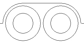
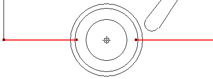
Press and hold the <Shift> key while indicating the two circles and the arc. Press the hot key <w> to start the Mirror function. Indicate the point over which to mirror the wheel:
Now press the hot key <8> to switch duplication to 'On'. Press hot key <7> to mirror over a straight vertical line. Proceed to press hot key <s> to move the selection closer towards the existing wheel. Indicate the following intersection point:
Proceed to draw a horizontal line from the top of the left arc to the top of the right arc using the latching icon for snapping perpendicular to both points:
Now proceed to trim all the extensive lines to complete the back wheel set. Use the <Enter> hot key to make use off the trim function multiple times in a row.
For enlarging the front wheel, lets start by clicking the icon Arc to Circle:
![]()
Indicate the arc to change it into a circle.
Now use the Change Radius function to change the outer radius into 140 and the inner radius into 90. Draw a new circle with a parallel distance of 20 to surround the outer circle.
Use the Trim function to trim the outer circle so that it will become an arc. When selecting the lines to trim from, press and hold the <Shift> key and indicate the lines one after the other:
Press <Enter> and then indicate the bottom half of the circle. Trim the remaining lines to complete the front wheel.
Now select the lines indicated in green using the Clump selection method. Press the hot key <l> to edit the line properties in the Properties window. Change the pen color of the selected lines to green.