Create Pillars
Start situation – Create Pillars
In this step you will explore the possibilities of the Bent Line to Pillar and Straight Line to Pillar functions. These functions can be used in two ways:
- Creating a bent or straight pillar by specifying pillar relations;
- Creating a bent or straight pillar by converting a spline, polyline or line.
For the "Bent Line to Pillar" function, you will use the first method, and for the "Straight Line to Pillar" function, you will use the second method.
After that, you will connect multiple pillars by using the L and T connection methods.
Overview of actions:
- Create bent pillar
- Convert straight line segments to pillars
- Turn pillar
- Connect pillars
End situation – Create Pillars
Additional description of actions:
- Turn pillar
Let's turn the pillar by clicking the icon Direction in View in the Modify section of the Pillars tab:
![]()
Proceed by selecting the pillar on the far right. Make sure the option Thickness direction is selected, and Body direction is de-selected.
Create Bent Pillar
Creating a bent pillar is similar to creating a bent profile, with the difference that profiles are always positioned onto a plate, while pillars can be created anywhere.
Let's create a new top view 5000 above base that extends from frame 21 to frame 31, and a Min. Breadth of -100. Here you will create a bent pillar by applying relations to other construction parts. Start by first clicking the icon Pillars on the Construction ribbon tab, followed by the icon Bent Line to Pillar in the Insert section of the Pillars tab:
![]()
![]()
As you will notice, the two panels that appear are similar to the panels given when creating bent profiles. Select the INP beam with a profile size of "180" and endshape type 'A' for both ends of the bent pillar. You will now be presented with the panel Bent pillar relations.
The Min. Length of the pillar will be FR22. Indicate the longitudinal bulkhead 6600 from CL for the Min. Breadth and use a parallel distance of 500 and a radius of 600.
The Max. Length of the pillar will be the bulkhead at frame 29, also with a parallel distance of 500, and the final relation is the Max. Breadth which is the longitudinal bulkhead at 3960 from CL.
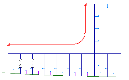
After defining these relations, please click the Preview button to see the result, as shown in the detail below:
Convert Line to Pillar
Now you are going to draw several 2D line segments, and then convert them into pillars.
Start the Line Segments function on the Draw tab:
![]()
Draw a line segment using the following coordinates:
Indicate first point: 23, 4000;
Indicate line length and angle: 800, 90;
Indicate line length and angle: 1600, 0;
Indicate line length and angle: 1000, -60.
Proceed to break the Line Segments function by using the hot key <Esc>, followed by the hot key <Enter> to restart the function:
Indicate first point: 24+300, 4000 and snap to the midpoint of the horizontal line segment using hot key <m>.
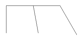
The result should look like the following:
Now click the icon Straight Lines to Pillar in the Insert section of the Pillars tab:
![]()
![]()
Select the Angle equal profile type with size "100" by "10", the body direction From Base and the thickness direction Towards CL \ From reversed frame. The endshape type will be 'A' for both ends of the pillar.
The selection panel Profiles appears and the hint bar tells you to Indicate vector that has to be changed into a profile. Draw a selection box around all four line segments to select them and click the OK button. The lines will now be converted into pillars.
Connect Pillars
There are two ways to connect pillars:
1. The 'L' connection: this is for where two pillar endshapes meet on a corner
2. The 'T' connection: this is for where one pillar endshape meets the side of a second pillar
Let's connect the outer two corners by using the "L" connection. Click the icon Connect Pillars -L in the Modify section of the Pillars tab:
![]()
The selection panel Connect Pillars - L appears:
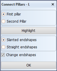
Start with the two pillars at the left corner. Draw a selection box around the endshape of the first pillar, and then do the same for the second pillar. Use the Slanted endshapes option in combination with the Change endshapes option and click OK. The endshapes are changed to type 'J' and the connection is made. Proceed to repeat this for the right corner.
Let's now connect the middle pillar with the top pillar by using the "T" connection. Click the icon Connect Pillars -T:
![]()
You are prompted to select the pillar to which to extend, in this case the top pillar. Then the selection panel Connect Pillars - T appears:
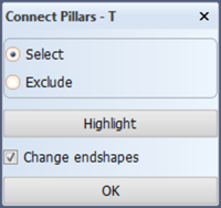
Proceed to draw a selection box around the endshape of the middle pillar. Use the Change endshapes option for a seamless connection and click OK. The connection is made.