Create Views
In the previous training step you have created a new block 108 and you indicated which blocks need to be drawn or dashed. Because you have opted to create the views already, the system gives you the possibility to create new views immediately after creating a new block.
The creation of new views is done in a fixed order:
- Create Top Views
- Create Side Views
- Create Frame Views
Create Top Views
In this training step you will create two top views "Deck 6200 above base" and "Deck 3500 above base".
Overview of actions:
- Create top views "Deck 6200 above base" and "Deck 3500 above base"
You will create two new top views "Deck 6200 above base" and "Deck 3500 above base" as part of the block creation process.
As mentioned before, a view has an area in which the construction will be shown. This area is specified by its values for the length, breadth and height. Always make this area bigger than the area of the construction in the current block. This way the construction of the dashed blocks will also be shown in your view.
Enter the values for the length, breadth and height of top view "Deck 6200 above base" in the panel Top View:
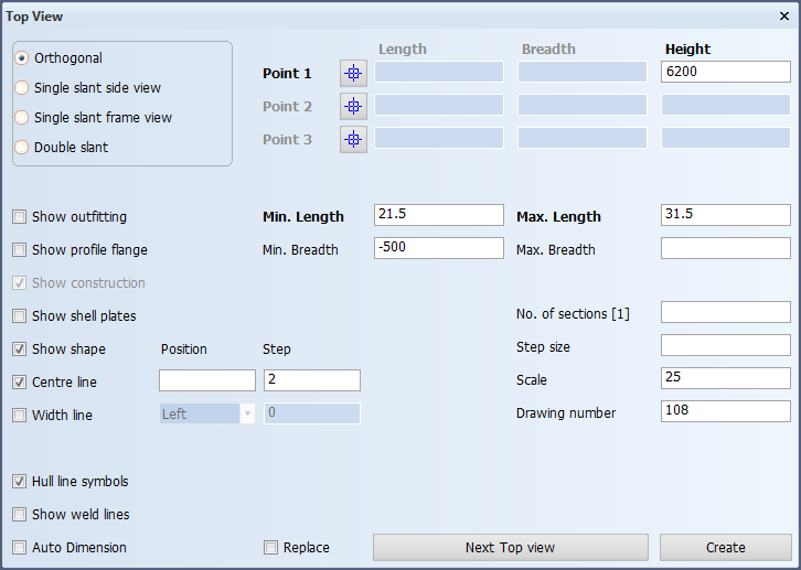
This panel contains three obligatory fields Height, Min. Length and Max. Length. Because this view is positioned at 6200 above base, the value for Height is 6200. The Min. Length and Max. Length are determined respectively by the frame number of the aft border and the frame number of the forward border with corresponding values 21.5 and 31.5.
Since you will only work on starboard, the optional fields Min. Breadth and Max. Breadth are also filled in. Because your plate will start 100 mm on starboard side and you also want to see part of the block on port side, the value of -500 should be entered for Min. Breadth. Unfortunately you don't know the exact value for Max. Breadth at the current position. If you don't know a value and you want the value to be determined by the hull line, you leave it blank by not entering any value.
If you are working on port side, the values for Min. Breadth and Max. Breadth are just the opposite. You enter 500 as value for Max. Breadth and leave the input field for Min. Breadth blank.
The following is a short explanation of the remaining optional fields:
- Only one top view of this size exists, therefore the value for No. of Sections has the default value "1";
- The default value "25" for Scale is used;
- The Drawing number stands for the block number and is automatically filled in;
- There are four types of views available: Orthogonal, Single slant side view, Single slant frame view and Double slant;
- Activating Show equipment will display the available equipment from piping;
- Activating Show profile flange will display profile flanges in a three line presentation instead of the default one line presentation;
- Activating Show shape will display the hull line;
- Activating Centre line displays the centerline where Position gives you the ability to enter an offset and Step to write a number at every second frame along the centerline. The default value for this is "2";
- The Replace option will be explained later on in this tutorial.
Since you have to create a second top view "Deck 3500 above base", you click the Next Top view button.

After clicking the Next Top view button, the same panel Top View appears again with the same values as default with the exception of the value for Height.
The second top view you want to create is "Deck 3500 above base" with a value of 3500 for Height. Now let's check the other values: only the value for Min. Breadth needs to be changed, because this view is not as wide as the previous view. Let's modify the value for Min. Breadth from -500 into 3500, meaning 3500 from centerline. Please click the Create button since this is the last top view that you are defining at this point. Now the specified top views are created.
Two top views have been created with their drawing names "108-6200" and "108-3500".
Create Side Views
After the creation of top views the system automatically gives you the possibility to create one or more side views.
In this training step you will create two side views "Long. Section 3960 off CL" and "Long. Section 6600 off CL".
Overview of actions:
- Create side views "Long. Section 3960 off CL" and "Long. Section 6600 off CL"
You will create two new side views "Long. Section 3960 off CL" and "Long. Section 6600 off CL" as part of the block creation process.
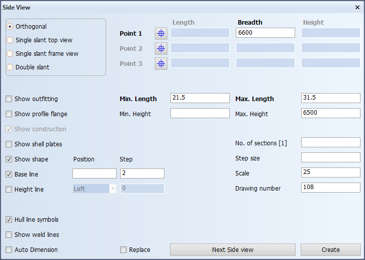
The first side view you will create is "Long. Section 3960 off CL" with the following values:

This side view is positioned at 3960 from centerline with a corresponding value 3960 for Breadth. The values for Min. Length and Max. Length are correct. Because the view must start from the hull line, no value is entered for Min. Height. The view should stop just above the upper deck "Deck 6200 above base" and therefore you should enter the value 6500 for Max. Height. Because you will make the side views one by one, please click the Next Side view button.
If you are working on port side, you only have to change the value for Breadth from 3960 into -3960.
Now the same panel Side View appears again with the same values except the value for Breadth. The second side view "Long. Section 6600 off CL" is positioned at 6600 from centerline, so the new value for Breadth is 6600. All the other values are correct. At the moment you will not create more side views, and therefore finish the creation of side views by clicking the Create button.
Two side views have been created with their standard drawing names "108-3960" and "108-6600".
Create Frame Views
After the creation of side views the system automatically gives you the possibility to create one or more frame views.
In this training step you will create eight frame views: "Frame 23" to "Frame 30".
Overview of actions:
- Create frame views "Frame 23" to "Frame 30"
You will create eight frame views "Frame 23" to "Frame 30" as part of the block creation process.
The eight frame views can be created in one action using the following values:
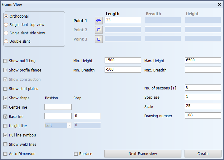
The value for Length in the case of frame views is not the value from aft perpendicular, but just the aft most frame number!
In this case the aft most frame number is 23. Officially the Min. Height could be left blank, meaning the view will start from the hull baseline, but the shape is rather high and you don't need the lower part of it. As a recommendation, please enter the value 1500 for Min. Height. The values for Max. Height and Max. Breadth are correct. Only the value for Min. Breadth must be changed from 3500 into -500, because all eight frame views will be created in one action.
The decision to make the views in one action means that the values 8 and 1 must be entered for No. of sections and Step size. Please make sure that the Base line and Height line checkboxes are unchecked and click the Create button to complete the creation of frame views.
As you can see in the dialogue window for output, the frame views are created one by one.