Deck 6200 Above Base
Start situation – Deck 6200 Above Base
Now you will start creating your first plate. When creating plates it is very important to determine the right sequence:
As seen on the sheet you have received for this tutorial, there are two main decks "Deck 6200" and "Deck 3500" and a longitudinal bulkhead "Long. bulkhead 6600" in between those decks. These decks should be created first, and then you should create the longitudinal bulkhead. This because then you can refer the bulkhead to the lower and the upper deck. This order of placement results in a so called topological connection: a relation between the plates.
Tip: Always try to achieve that a new plate can be related to existing plates!
That's why you will start with creating the upper deck "Deck 6200 above base". This deck consists of one plate with a thickness of 8 mm.
Overview of actions:
- Clear the screen if at this point you already have opened a drawing. This can be done by clicking the Blank drawing button on the toolbar.
- Open drawing top view "108-6200"
- Place standard text "Deck 6200 above base" above the view
- Create plate "Deck 6200" with a thickness of 8 mm but without cutout
Later on you will create the necessary cutout by modifying the plate contour.
End situation – Deck 6200 Above Base
Additional description of actions:
- Open drawing top view "108-6200"
Opening drawing top view "108-6200" is similar to opening drawing frame view "108-27", but you have to select "Top" as type of view and "108-6200" as drawing name in the panel Open.
Adding Text
Recommendation: Place standard text in the view before you start creating any structure
When there is too little space above the view to place the standard text, the view needs to be shifted down by using the "PAN" option. There are two ways to go about this:
1. Press and hold down the mouse wheel while moving the mouse
2. Hot key: <Ctrl> + Mouse
Please select the Draw ribbon tab.
When there is enough space above the view to place the standard text, please click the Text button in the Text section on the Draw ribbon tab:
![]()
After selecting this function, the panel Text appears:
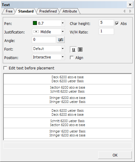
To place standard text above a view, you only have to select one of the text lines. In this example please select the text "Deck 6200 above base". The selected text will appear in the graphical screen. When the option Position is set to Interactive, by means of the mouse you can indicate the position where you would like to have the text placed. You can reposition the text afterwards by using the hot key <z> in combination with the mouse.
Next, you want to have everything back to full screen. You can use the function Full Screen on the View tab for this or the keyboard shortcut <5>:
![]()
Create Plates
Now you will create your first plate "Deck 6200" without cutout.
One of the most frequently used functions within CADMATIC Hull is the creation of plates. The plate creation function has a considerable number of options, due to the fact that plates can have very different shapes. During this tutorial you will create several plates with an increasing level of complexity. Each plate has a specified thickness and contour.
Within the current application 3D-Contek, the plate will always be situated in the plane of the current view. Within CADMATIC Hull plate boundaries must be defined counterclockwise.
Examples of possible plate boundaries are:
- Hull shape;
- Plates and profiles;
- Local horizontal and vertical limitations;
- Lines and arcs drawn by yourself.
Select the Construction tab and click the Plates button to open the Plates ribbon tab:
![]()
Proceed by clicking the icon Plates in View:
![]()
After selecting this icon, the panel Plates in View appears:
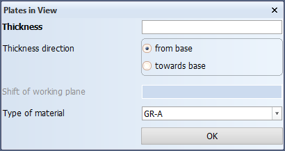
This panel contains one obligatory field Thickness and three optional fields Thickness direction, Type of material and Shift of working plane. Only the values for Thickness and Thickness direction will be of concern during the tutorial. In this case plate "Deck 6200" has a thickness of 8 mm and the thickness direction is from base. After accepting these values by clicking the OK button, you have to specify the plate boundaries, that is, the plate relations by means of the panel Define a plate contour.
Overview of basic rules for the specification of plate relations:
- The plate relations must be defined counterclockwise;
- Generally, the indication point of an item to be related, is at the side where the plate will be created;
- The starting boundary of a plate can be arbitrarily selected.
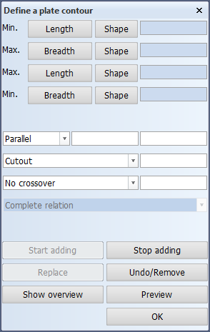
The relations of plate "Deck 6200" without cutout will be defined as follows:
- Start with the aft boundary of the plate and click the Min. Length button. The aft boundary is located 100 mm beyond frame 22 (at the fore ship side). This value must be entered as 22+100 for Min. Length;
- Applying the rule that plate relations must be defined counterclockwise, the next boundary of the plate is the hull line. This relation can be defined by applying an indication point inside the hull in the graphical window;
- The next relation is the forward boundary of the plate located at frame 31. Click the Max. Length button and enter 31 as value in the entry field;
- The last boundary of the plate is a line with a parallel distance of 100 mm from the centerline. Click the 'Min. Breadth' button and enter 100 for the value in the entry field.
The following rules can assist you in determining the type of length (minimum or maximum) for a certain definition:
- If there will be plate material (of the plate to be created) present on the right side of the boundary, this definition is named the Minimum Length;
- If there will be no plate material (of the plate to be created) left on the right side of the boundary, this definition is named the Maximum Length.
After defining all boundaries of the plate "Deck 6200" you can preview the result by clicking the Preview button. Only by clicking the OK button, plate "Deck 6200" is actually created!