Frame 29 – Part 3
- Create Vertical Profiles
- Change Direction of Profiles in View
- Change Endtype of Profiles
- Lengthening Profiles
- Trim / Extend Profiles
- Shift Profiles
- Create Profiles in View
- Create Brackets Type A
- Reposition Text
After the creation of one lower plate and two upper plates, you will add the following construction parts:
- The upper stiffeners HP 220 x 10 between decks "Deck 3500" and "Deck 6200";
- The lower stiffeners HP 220 x 10 between the hull and the lower deck "Deck 3500";
- The transverse deck beam HP 140 x 8;
- A bracket between deck beam and transverse bulkhead "Bulkhead Fr. 29".
Finally you will dimension the decks, the deck beam, the bulkhead and the stiffeners.
Overview of actions:
- Create upper stiffeners at 4620, 5280 and 5940 off CL
- Modify direction of upper stiffeners at 4620, 5280 and 5940 off CL
- Modify end types of upper stiffeners at 4620, 5280 and 5940 off CL
- Modify length of upper stiffeners at 4620, 5280 and 5940 off CL
- Create the upper stiffener at 7250 off CL
- Create lower stiffeners at 4620, 5280 and 5940 off CL
- Modify length of lower stiffeners at 4620, 5280 and 5940 off CL
- Create lower stiffener at 6600 off CL
- To bring this lower stiffener in line with the bulkhead, shift lower stiffener at 6600 off CL 10 mm to starboard
- Create transverse deck beam at FR29
- Create bracket "A 02" between deck beam and transverse bulkhead
- Reposition text "Frame 29" above view
After finishing this view, you will return to the longitudinal section "Long. section 3960 off cl" to finish that view.
Additional description of actions:
- Create the upper stiffener at 7250 from CL
The creation of one upper stiffener at 7250 from CL is similar to the creation of upper stiffeners at 4620, 5280 and 5940 off CL with the following properties:
|
Name of panel |
Option |
Value |
|---|---|---|
|
Create profile |
Selected profile type |
|
|
|
'Body size' |
220 |
|
|
'Thickness' |
10 |
|
|
'From breadth' |
7250 |
|
|
'Body direction' |
Towards reversed frame |
|
|
'Thickness direction' |
Towards CL |
|
|
Molded side placement |
Default |
|
|
'Type of material' |
GR-A |
|
Border value |
Limitation |
First limitation |
|
|
|
Indicate the lower deck |
|
|
'Vertical distance' |
40 |
|
|
'1st end shape' |
|
|
End type |
'Angle of edge' |
60 |
|
|
'Nose height' |
25 |
|
Border value |
Limitation |
Second limitation |
|
|
|
Indicate the upper deck |
|
|
'Vertical distance' |
40 |
|
|
'2nd end shape'
|
|
- Create lower stiffeners at 4620, 5280 and 5940 off CL. For these profiles, you will use the grid to indicate where the profiles are to be placed.
By pressing the hotkey <2>, you will set the grid visible in the graphical screen. With hotkey <Ctrl + G>, you open a panel in which you can select which grids to show. Clicking the grid with the left mouse button will determine the value for 'From breadth' and clicking the grid with the right mouse button will determine the value for 'To breadth'. Let's proceed to create the profiles according to the following properties:
|
Name of panel |
Option |
Value |
|---|---|---|
|
Create profile |
Selected profile type |
|
|
|
'Body size' |
220 |
|
|
'Thickness' |
10 |
|
|
'From breadth' |
Click the grid with left mouse button at 4620 |
|
|
'To breadth' |
Click the grid with right mouse button at 5940 |
|
|
'Number of items' |
3 |
|
|
'Body direction' |
Towards reversed frame |
|
|
'Thickness direction' |
Towards CL |
|
|
Molded side placement |
Default |
|
|
'Type of material' |
GR-A |
|
Border value |
Limitation |
First limitation |
|
|
|
Indicate the hull line |
|
|
'Parallel distance' |
40 |
|
|
'1st end shape' |
|
|
Border value |
Limitation |
Second limitation |
|
|
|
Indicate the lower deck |
|
|
'Vertical distance' |
40 |
|
|
'2nd end shape'
|
|
|
End type |
'Radius' |
35 |
- Create lower stiffener at 6600 off CL according to the following properties:
|
Name of panel |
Option |
Value |
|---|---|---|
|
Create profile |
Selected profile type |
|
|
|
'Body size' |
140 |
|
|
'Thickness' |
8 |
|
|
'From breadth' |
6600 |
|
|
'Body direction' |
Towards reversed frame |
|
|
'Thickness direction' |
Towards CL |
|
|
Molded side placement |
Default |
|
|
'Type of material' |
GR-A |
|
Border value |
Limitation |
First limitation |
|
|
|
Indicate the hull line |
|
|
'Parallel distance' |
40 |
|
|
'1st end shape' |
|
|
End type |
'Angle of edge' |
60 |
|
|
'Nose height' |
25 |
|
Border value |
Limitation |
Second limitation |
|
|
|
Indicate the lower deck |
|
|
'Vertical distance' |
0 |
|
|
'2nd end shape'
|
|
|
End type |
'Radius' |
35 |
Create Vertical Profiles
Before you can make the upper stiffeners, take a look at the second sheet. This sheet contains the longitudinal sections 4620, 5280 and 5940 off CL with details of the stiffeners on the bulkhead at frame 29.
Note: During the creation process of these stiffeners, you will deliberately make some mistakes in order to practice the modification of these stiffeners afterwards!
You will create the upper stiffeners HP 220 x 10 at 4620, 5280 and 5940 from CL in one action.
Select on the 'Construction' tab the icon Profiles:
![]()
Select the icon Vertical Profiles in the Insert section of the Profiles tab:
![]()
You specify the type of profile and its position by means of panel Create Vertical Profile:
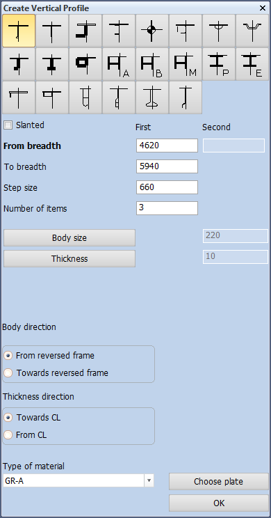
Because you are already familiar with the options within this panel, only the values of these options will be given here:
- The type of profile is "HP" or "Bulb" and therefore the following option icon is selected:
![]()
- The size of the profiles is HP 220 x 10, thus the values for Body size and Thickness are 220 and 10;
- The first and last profiles are located at 4620 and 5940 from CL respectively, thus the values for From breadth and To breadth are 4620 and 5940. Now you can continue by either entering the step size or specifying the number of items. Of course you can calculate the step size, but it's easier to fill in the number of items. So enter value 3 for Number of items. The step size will be automatically calculated by the program;
- For now accept the presented default values From reversed frame and Towards CL for the options Body direction and Thickness direction. Later on you will verify these directions. If they turn out to be wrong, you will use the profile modification options to correct them;
- Accept the default value for Molded side placement.
- The type of material of the profiles will be the standard material 'GR-A'.
After clicking the OK button, you have to specify the length of the profile by defining its start and endpoint. It's preferable to start with the lower end.
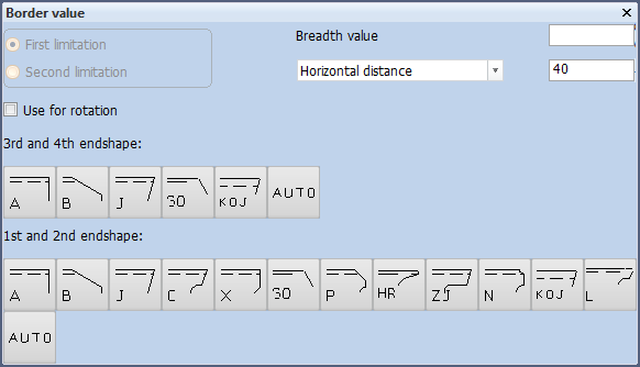
First you determine the lower end of the profile by means of panel Border value:

According to the hint Indicate 1st relation you select the lower deck "Deck 3500" by clicking a fraction above this deck. Although the vertical distance should be 0 mm, you will leave it at 40 mm. Then you need to select the end shape: the correct one should be type 'C' but please select 'A' for now.
Secondly you determine the upper end of the profile:

According to the hint Indicate 2nd relation you select the upper deck "Deck 6200" by clicking a fraction below it. The vertical distance is 40 mm. Please select type 'A' as the second end shape.
After selecting the second end shape, three profiles of type HP 220 x 10 will be created at 4620, 5280 and 5940 from CL.
Change Direction of Profiles in View
Now you will change the direction of the three created upper profiles HP 220 x 10.
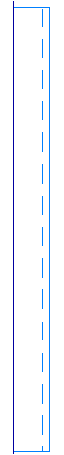
You can see that the profiles are displayed as continuous lines, meaning that the profiles are located on the aft side of the bulkhead. When you look at the sheet, you will notice that the profiles are on the front side of the bulkhead, which are illustrated with dashed lines.
In the Modify section of the Profiles tab, which should still be open from the previous step, there are two options for changing the direction of profiles:
- Change direction of profile in view:
![]()
- Change direction of profile in section
![]()
The first option is used for profiles in view as illustrated here:

The second option is used for profiles in section, like this one:

Since the upper profiles are profiles in view, you select the option icon Direction in View from the icon. You can also right click on the profiles to open the modification panel.
By means of panel Profile Selection you select the profiles using the Conflict selection method:
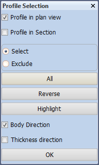
You select the three upper profiles, by dragging a selection box from right to left across the profiles. After selecting these, the profiles will light up for a short time.
The lower part of this panel offers two modification options: Body direction and Thickness direction and the OK button to carry out the modification(s).
In this case the thickness direction of the profiles is correct since they are pointing to CL, but the body direction is not. Check Body direction and uncheck Thickness direction and click the OK button to change the body direction of the selected profiles.
Change Endtype of Profiles
As you know the three upper profiles HP 220 x 10 have been created with the following faults:
- They have the wrong direction;
- At the lower end they are too short;
- At the lower end they have the wrong end types.
Now you will start modifying these profiles. There are several different ways to approach the modify functions for profiles:
- Selecting the icon Profiles on the Construction tab
- Indicating a profile in the graphical screen
Selecting the Profiles icon on the Construction tab, as well as indicating a profile in the graphical screen with the left mouse button, will display the Profiles ribbon tab:
![]()
This toolbar contains a lot of modification options. During the tutorial, you will use the following ones:
- Change end type of profile
![]()
- Change direction of profile in view
![]()
- End relation
![]()
- Trim / Extend
![]()
- Shift Profile
![]()
- Change size / type of profile in view
![]()
- Turn profile
![]()
Indicating a profile by right clicking it in the graphical screen results in the following popup:
![]()
Let's start with the modification of the end types by selecting option End Type:
![]()
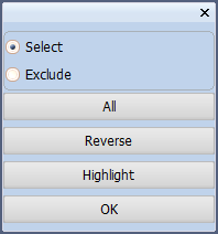
By means of panel Profiles Selection you select the profiles using the 'Clump' selection method or you can right click on the profile:
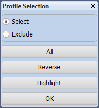
With this option, you need to drag a selection box around the lower ends of the profiles in such a way that the end flags are included within this box. After selecting all three ends, you click the OK button.
Now select the correct end type in panel Change endshapes:
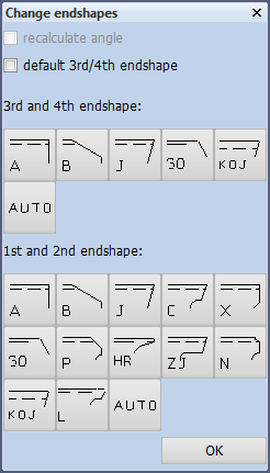
In this case choose end type 'C':
![]()
This end shape contains a small welding hole in the corner. You enter the value 35 for the radius of this hole with in the presented panel End type:

After selecting the OK button, the lower end shapes of the profiles will be modified from type 'A' into type 'C'.
Lengthening Profiles
Regarding the three upper profiles HP 220 x 10, the length of these profiles is still incorrect. At the lower end, the profiles are 40 mm too short.
In the Modify section of the Profiles tab, two options are available for changing the length of the profiles:
- Trim / Extend
![]()
- End relation
![]()
The first option Trim/Extend changes the length of the profile with a fixed value; positive for lengthening and negative for shortening, whereas the second option End Relation changes the length of the profile by means of a reference line; by selecting a reference line, the profile will be extended or reduced to this line.
You will now select the option End Relation:
![]()
By means of panel Profile End Relation Selection, you select the profiles using the 'Clump' selection method:
Because the profiles must be extended at the lower ends, you should drag a selection box around these lower ends in such a way that the end flags are all included in the box. After selecting these profiles select the OK button.
Select the upper side of the deck "Deck 3500", and you accept the value 0 for Vertical distance from this relation in panel Trim/Extend profiles:
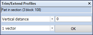
Select the OK button to extend the upper profiles to the lower deck "Deck 3500".
Trim / Extend Profiles
Looking at the lower profiles HP 220 x 10 at 4620, 5280 and 5940 off CL you will notice that these profiles are positioned with a 40 mm distance between their upper ends and the deck, while there should actually not be any distance there. To fix this situation, you are going to use the modify options once more in order to lengthen the profiles by 40 mm.
Right click a profile in the graphical screen and select Trim/Extend (which changes the length of profiles with a fixed value) instead of the option End Relation:
![]()
Now you are presented with the panel Trim/Extend Profiles as here below:
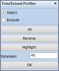
To select the lower profiles you need to draw a box around the upper ends in such a way that the end flags are partially included in this box. To extend the selected profiles, you enter 40 as value for Extension and click the OK button to lengthen the profiles.
The lower profiles HP 220 x 10 will be extended by 40 mm with the result that they are now touching the lower deck "Deck 3500".
Note: Specifying a negative value would shorten the profile.
Shift Profiles
Although at first glance the lower stiffener HP 140 x 8 at 6600 from CL looks correct, its position is not in line with the bulkhead "Long. bulkhead 6600" due to a difference in thickness direction. The thickness directions of the bulkhead and the stiffener are defined as From CL and Towards CL respectively.
You can bring the lower stiffener in line with the bulkhead by moving (shifting) the stiffener 10 mm to starboard:
Click on the "Shift" button in the Modify section of the Profiles tab:
![]()
By means of panel Shift Profiles, you select the profile using the 'Cross hair' selection method:
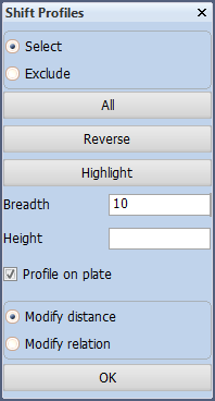
By checking the option Profile on plate, you make sure the profile stays on the same plane as the plate to which it belongs.
To shift the selected profile 10 mm to starboard, you enter value 10 for Breadth and select the OK button, the profile will be shifted 10 mm to the outside.
Note: After shifting the lower stiffener HP 140 x 8, it will keep all its relations, meaning that the distance to the hull line will remain 40 mm, due to the fact that the stiffener is topological!
Create Profiles in View
There is still a transverse deck beam to be created. So far all deck beams have been created in the top view of the upper deck. This has two reasons:
- It gives you the possibility to create a series of profiles in one move within that particular view, which saves time.
- You should always try to complete a view as much as possible while you are working on that view, which also saves time in terms of switching drawings.
Now you will create the transverse deck beam in the current frame view by using the option Profiles in View in the Insert section of the Profiles tab:
![]()
![]()
According to the hint Indicate the hull line/plate you select the upper deck plate. By means of panel Create Profile you specify the type of profile and its directions:
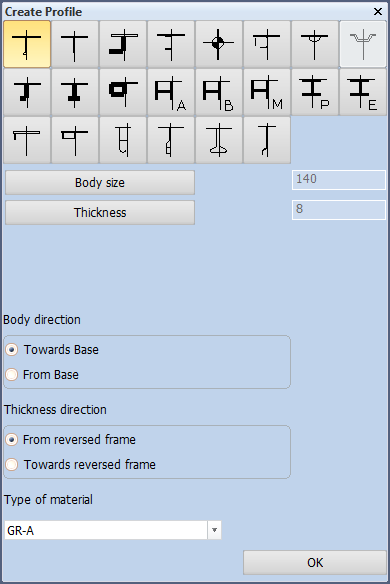
The selected profile size and directions are correct and therefore you can click the OK button to accept them. Now you are able to define the first and second relation of the profile.
Since there are no plates or profiles available around centerline that could be used as a relation for the first limitation, you need to enter the value 100 for Breadth value in panel Border value to define the first limitation at 100 mm from centreline:
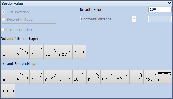
You define the end type for this end by selecting type 'C' as the first end shape:
![]()
The welding hole of this end shape has a radius of 35 mm:
Click the OK button in panel End type to accept the first limitation.
Now you specify the second relation by indicating the existing upper bulkhead "Bulkhead Fr. 29" on the left hand side as shown below:
The horizontal distance from the bulkhead in panel Border value will be 40 mm:
Finally, you define the end type by selecting type 'A' as the second end shape:
![]()
Now also the second limitation is determined, resulting in the creation of the transverse deck beam HP 140 x 8.
Note: The option Profiles in View has one restriction: you can only create one profile at a time!
Create Brackets Type A
You will now create a standard bracket of type A between deck beam HP 140 x 8 and the upper transverse bulkhead "Bulkhead Fr. 29".
Select on the Construction tab the icon Brackets:
![]()
![]()
Now select the icon Brackets in Plan View in the Insert section of the Brackets tab:
![]()
The system will display panel Insert Brackets in Plan View, which contains default bracket types delivered by NCG:
![]()
The brackets provided by NCG are as follows:
- Standard brackets;
- Brackets 'fit to the situation'.
The "Standard brackets" have fixed dimensions, meaning that the user can only select the bracket dimensions from predefined lists with standard dimensions. The following brackets belong to this group:
- Bracket type 750
![]()
- Bracket type 751
![]()
- Bracket type 752
![]()
- Bracket type 753
![]()
- Bracket type 754
![]()
- Bracket type 755
![]()
- Bracket type 770
![]()
All the other brackets belong to group Brackets fit to the situation and have no fixed dimensions. The user can either accept the presented default dimensions or specify his own dimensions.
Now you will create the bracket between deck beam HP 140 x 8 and the upper transverse bulkhead "Bulkhead Fr. 29". In this situation you need to use standard bracket "A" with overlapping on one side at the deck beam. On the other side the bracket will touch the bulkhead.
Select bracket type 'A':
![]()
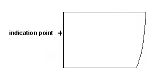
As the first hint suggests; Indicate a part (or profile, to where no overlap) you indicate the bulkhead at a position just outside of the plate. Then a second hint Indicate profile at position where overlap has to be placed is displayed. Because the overlap should be placed at the deck beam, you indicate the deck beam at a position just below it.
The locations of both indication points are illustrated in the figure below:
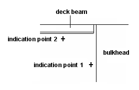
By indicating the bulkhead and deck beam you are defining the first and second relations of the bracket. After defining all the relations, you will be presented with the main panel for the selected bracket type "Bracket type 750" :
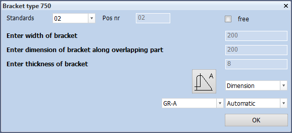
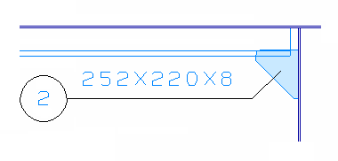
For this bracket type the system automatically calculates the bracket dimensions according to the profile height. Each standard set of dimensions has a predefined part number, which is presented as Standards. Please click the OK button to accept the settings for "Bracket type 750":
The bracket will be created with "2" for the part number:
Reposition Text
You will reposition the standard text "Frame 29" above the view in order to create enough space for the placement of dimensions as shown on the drawing.
Before you can actually reposition text "Frame 29", the view needs to be moved down by using the function "PAN":
Hot key: <Ctrl> or the mouse wheel
Press and hold the key <Ctrl> and move the view by moving the mouse at the same time to drag the view to the desired location. Press and holding the mouse wheel has the same effect.
Now that there is sufficient space above the view, you can reposition text "Frame 29" by using the following method:
- Select the text by positioning the cross hair over the text and left-clicking it (or press the <SPACE> bar): the selected text will be highlighted;
- Press the hot key <z> and move the text upwards by using the mouse to drag the text to the desired position;
Use the ribbon icon Full Screen in the View section of the View tab to see the whole drawing on screen:
![]()
![]()
Hot key: <5>