Use of the 3D Hull Viewer
Now you will start the Hull Viewer application to view the active block in a 3-dimensional environment.
Overview of actions:
- Show active block
- Viewpoint projections
- Presentation of parts and the viewing modes
- Item information
- 3D-Contek interactivity
- Navigation settings for various ways to view the block
- Filter options to filter various part properties
Additional description of actions:
- Show active block
To show the active block in Hull Viewer, select the icon Hull Viewer in the General section of the ribbon:
![]()
Hull Viewer will now start up and display 3D models of the parts you have created thus far.
- Viewpoint projections
To the left of the screen there is a toolbar present with 14 predefined viewing perspectives to choose from. These perspectives are set to certain angles relative to the block you have open in Hull Viewer. When you imagine a cube around the block, that cube will have 6 sides to it. The first 6 buttons take you to the viewpoints perpendicular to those sides. The remaining 8 buttons are set to the viewpoints in each corner of the cube.
- Item information
The same menu you open by right clicking a part, also contains the function Item information. When selecting this, the system displays the panel 3D-Item information with geometric information about the part you selected. More about this will be explained later on in the tutorial. Next to geometric information for an item, also logistical information, attribute information and additional information can be retrieved using this panel.
Presentation of the Parts
You can select a part by clicking on it once. When you hold down the <Shift> key and click on the part again, it will be de-selected. Pressing and holding down the <Shift> key also allows you to select multiple parts, by clicking on them one at a time.
You can also invert your selection with the hotkey combination <Ctrl> + <R>. Using <Ctrl> + <A> will select the entire block. Doing the same in combination with the <Shift> key will deselect the block.
When you right click a part, you will be presented with a menu. Here you see the functions Hide part, Transparent, Wireframe and X-Ray.
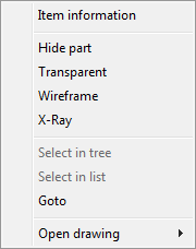
Setting a part to Transparent allows you to see what is behind it. Setting a part to Hide allows you to select what is behind it. For Wireframe see "Viewing mode" below. Setting a part to X-Ray allows you to see it at all times, even through other parts. In order to restore the parts after you have used these functions, you can either open the View menu, or you can use the following buttons:

Respectively, these are Restore hidden, Restore Transparent and Restore X-Ray.
Viewing mode

There are two different modes in which you can view your block: Shaded being the standard viewing mode in Hull Viewer. Wireframe only displays the contours of the parts, which will help increase performance when dealing with very large models.
3D-Contek Interactivity
Show drawing box
If a drawing exists for a certain part you select, and the field Drawing name is present in the logistical layout, it will be displayed in the right mouse menu under Open drawing. Selecting this will open the drawing in 3D-Contek. The function known as the "drawing box" will display which drawing you have open in 3D-Contek. This transparent "box" also represents the defined drawing area of that particular drawing.
To activate the drawing box, select the icon Toggle drawing box:

Select it again to switch it back off.
Clipping
When you wish to focus on a part that is hard to see because it is located deep within a block and various parts are blocking the view, using this function will allow you to trim the view of your displayed block in length, width, and height.
Select the icon Clipping:

You are presented with the panel Clipping:
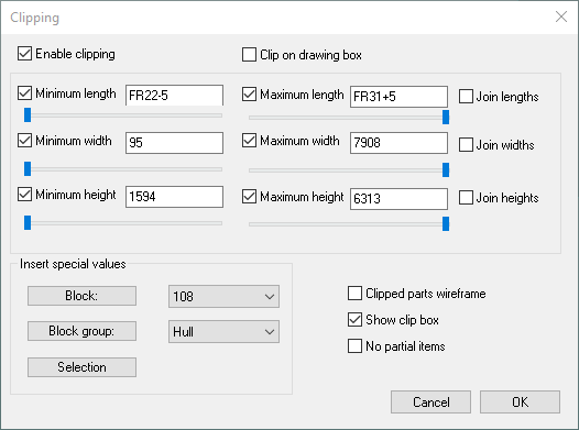
You can either use the slidebars, or input a value to indicate the location of the part you wish to isolate. Using the option Clip on drawing box will automatically trim the block to where you only see what is displayed inside the drawing box.
Now you are going to increase the viewing distance in length by means of the panel Drawing Properties in 3D-Contek, after which you will use the clipping function to see the effect.
Open the panel Drawing Properties in 3D-Contek by selecting the ribbon icon in the General section:
![]()
Proceed by clicking the Visibility button:

The panel Visibility is displayed:
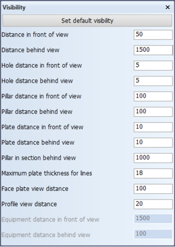
Change the value for Distance behind view from 50 to 1500 and click the OK button on the Drawing Properties panel. Now activate the drawing box in Hull Viewer by clicking the Toggle drawing box icon:
As you can see, the drawing box has now increased in length. Now you activate the clipping function by selecting the icon Clipping:
Activate the option Clip on drawing box. Now everything within the drawing box is visible, while everything outside of it is hidden.
To continue with the tutorial, please change the Distance behind view in the Visibility panel back to 50.
Navigation Settings
The following buttons are used to control the navigation settings:

Spin is the standard navigational use. You can spin the block around to view it from any angle you wish. This function has a number of control keys to use:
-
Pan function 1 – Ctrl + mouse movement
-
Pan function 2 – Hold down mouse wheel + mouse movement
-
Zoom function 1 – Mouse wheel
-
Zoom function 2 – Hold down mouse wheel + left mouse button + mouse movement
-
Rotate in any direction 1 – Ctrl + Shift + mouse movement
-
Rotate in any direction 2 – Left mouse button + right mouse button + mouse movement
By default the center of rotation is the center of the block. You can re-focus the center of rotation to make the block revolve around any point on a part you indicate. You can do this by using the hotkey <C> at any given time.
Walk allows you to move around the section using the mouse. Pressing the left mouse button in Walk mode will result in the mouse pointer jumping to the center of Hull Viewer. The distance between this center and the point to which you move the mouse while pressing the left mouse button defines the speed of the view change. There are three different ways of controlling the view point and direction in walk mode:
-
Moving and turning
By moving the mouse away from the center, you move your point of view. Moving the mouse upwards or downwards will move your viewpoint forward or backwards. Moving the mouse to the left or to the right will turn your point of view to the left or to the right.
-
Shifting
By pressing the <Shift> key and the left mouse button, your point of view can be shifted horizontally or vertically depending on the movement of the mouse.
-
Tilting
By pressing the <Ctrl> key and the left mouse button, you can change the angle of view. Only the vertical movement of the mouse has effect.
Orbit allows you to put the block in an indefinite spinning motion. Click and hold the mouse, and then move it in the direction you wish it to spin. Release the mouse button at the end of your movement. The speed at which the block will spin depends on the speed of your movement.
Filter Options
You can visually filter the block using 5 different types of criteria:
-
Thickness of parts
-
Type of material of parts
-
Orientation to parts
-
Nesting status
-
Logistical properties
The effect of the filter is expressed in a certain color. Parts with an equal thickness will have the same color when using the Thickness filter. The Material filter will render parts of equal material the same color. Parts of which the thickness points into the same direction (i.e. towards/from centerline, or towards/from base) are given the same color when using the Orientation filter. The Nest status filter gives plates that have nesting information present a different colour. The Logistical colour filter can visualize logistical properties of parts according to criteria that is user defined. These functions are found with the following buttons:

The remaining button stands for No Filter, which represents the standard viewing mode.