Erection lines
Users can specify that the end of a weld line should be used for block erection by using the Construction > Welds > Modify > Split Weld > Erection Weld function. This is used for indicating an area near a block border which should be welded at a later stage than the remainder of the weld line. This function allows users to split off a length of the weld line from the block border for one or multiple weld lines on profiles and/or pillar-profiles in the active block, instead of requiring them to split the weld lines individually. The drawing should contain weld lines. Use the Drawing Properties function to get them from the database if they are not present in the drawing. When the user starts the function, the following window opens:
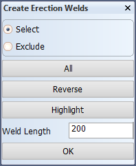
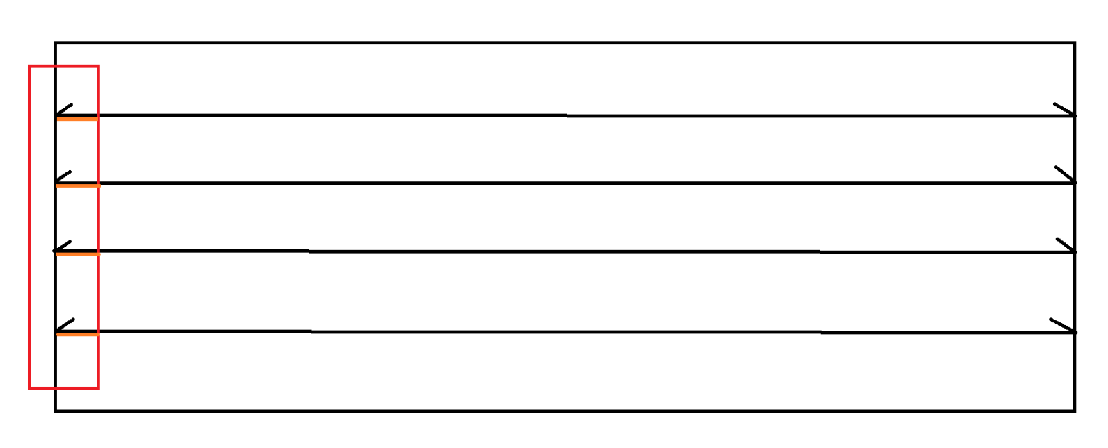
The user can select multiple weld lines with this dialog open and can also specify the length of the weld line which will be split off to serve as an erection line by using the Weld Length input. This value begins with the default value set by the system administrator using the Construction > Welds/Bevels > Weld Lines > Erection Weld Length setting in the System Management application. After running the function, the weld line on the profiles will be split as shown in the image below , where the orange lines represent the erection weld lines.