Adding weld dimensions
The Weld Dimension function for adding weld dimensions can be started from the following menu locations.
3D-Contek application:
- Draw > Symbols > Weld Dimension
- Construction > Welds > Labeling > Weld Dimension
Shell application:
- Draw > Symbols > Weld Dimension
- Construction > Symbols/Dimensions > Labeling > Weld Dimension

To add weld dimensions to the drawing, do the following:
-
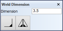
Select the weld symbol, and enter the desired value(s) in the input field(s) in the Weld Dimension dialog.
-
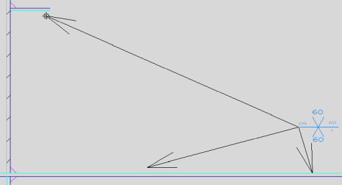
Click on a line to set the starting position of the lead line. This end of the lead line will get an arrow.
-
Click on another position to place the other end of the lead line. This determines the direction of the lead line. The weld dimension with the lead line, indication line, and line length is placed.
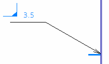
The length is calculated automatically if it is not entered in the Weld Dimension dialog. The system remembers the last entered value, so you must clear the value the next time if you want the system to calculate the length.
Note: The length of the line or arc is shown in the weld dimension if the used weld symbol includes the text WeldLength or + Length.
You can duplicate the dimension, i.e. have two or more dimensions with the lead lines starting from the same point: Select the dimension and then click on the position where to place the duplicate. Repeat to add more dimensions.
Changing the orientation
Weld dimension can be turned by 180 degrees and rotated 90 degrees with the following Function dependent options:
- 6 = Turn
- 7 = Rotate
Repositioning
- Right-click anywhere in the graphical window, and select Manipulate > Interactive Move.
- Select the weld dimension, and press Enter.
- Drag the weld dimension to the desired position and orientation, and click to place it.
Adding arrows
Select the weld dimension at the weld symbol side. A new arrow will appear, and it can be dragged to a new position.