Weld and beveling related settings and rule files
There are several files related to weld and beveling settings and norms. These files are used to store System Management settings, or they are called from various macros or program code. The files are centralized in one location in the project norms: <project>\norms\cvar\weld. Files for the weld and beveling rules are also stored in this location.
Note: These files were relocated to the current location in the 2021T2 release of CADMATIC Hull. Previously they were located in the active norms folder %ncgnorms%, and it was possible to have several of these norms folders in a project. Now all the weld and beveling related settings and norms files are located in a single location and are used throughout the complete project. When a project created with a Hull version earlier than 2021T2 is opened in Hull 2021T2 and later, the system automatically copies the files from the norms folder that is the most used by block groups to the new location.
Using different settings for different block groups
In situations where blocks for the same ship are produced at different facilities using different settings and norms, it is possible to make own weld and beveling rules for different block groups. The blockgroup variable can be used in the rules for this purpose. This way all the rule files can be stored in the same location.
For information on how to use the blockgroup variable, see Handling block groups in beveling rules.
Settings and rule files
The project norm folder <project>\norms\cvar\weld contains the following files and folders by default.
-
\bvl\ – Folder for predefined bevel models and related files
-
\bvl\dxf\* – Folder for models for bevel symbols used in DXF output
-
bevel_hull.cfg, bevel_plan.cfg and bevel_sect.cfg – Old bevel rule files for connections to hull, in plan view, and in cross-section. Not used in Hull 2021T1 and later versions. Instead, pdbrule*.cfg files are used.
-
bevel5.cfg – Bevel presentation
-
beveltypes* – Bevel configuration file for the standard bevel types
-
calcweldinfo.cmd – User defined macro, enables the showing of weld data in Work BreakDown sketches. See calclweldinfo.cmd below for more information.
-
main* – Welding codes
-
pdbrule*.cfg – Plate bevel rules
-
pdbtypes12.dat – Profile end type bevels for the 1st and 2nd end shapes
-
pdbtypes34.dat – Profile end type bevels for the 3rd and 4th end shapes
-
profilepdb*.cfg – Profile bevel rules
-
ps_*.mod – Weld label models
-
settings.dat – Shrinkage factors for profile types
-
shrinkage.dat – Shrinkage compensations for welds
-
weldmgr.cfg – Weld Manager configuration file
-
weldfactor*.cfg – Weld factor rules
-
weldlabel.ins – Specifies weld label models. A weld label model is defined as a combination of bevel type and weld method.
-
weldside*.cfg – Weld side Rules
This user-defined macro enables the showing of weld lines and including a weld table in Work BreakDown 3D sketches. See Showing weld lines for information on how to include weld data in the WBD 3D sketches.
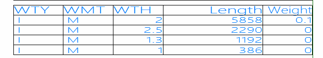
The system calculates the total weld lengths and weights by using the macro. The totals are included in the WBD 3D sketch in a table that shows all weld lines of the same type, method, height (throat) and length on a single line with the totals.
The data to include in the table must be defined in this macro. Only the weld data for which keywords are included in the macro is presented in the weld table.
The macro contains the following labels:
-
init – Defines the variables wtotal and ltotal for total weights and lengths.
-
calc – The calculation of the total weights and lengths is based on this.
Keywords are available for the weld type (WTY), weld method (WMT), and weld height (WTH) and length (WTL).
-
tableline – Defines the position of the calculated totals in the table.
-
tableheader – Defines the header of the table.
The macro determines the position in the drawing and places the text with certain characteristics in this position and draws the lines using the following variables:
-
wtotal – Provides the total weld length for a certain bevel type. This is shown inside the table. The wtotal calculation takes into account the weld height and length.
-
ltotal – Defines the number of lines in the table.
-
t – Defines the text content using the keywords.
The macro must be located in the weld folder of the project norms (<project>\norms\cvar\weld). An example macro is included in the default norms.
label init
Numeric Wtotal,Ltotal
Wtotal=0
Ltotal=0
move p0
exit
label calc
arguments string infoline
{
# 'calcweldinfo in -ncgnorms/weld/calcweldinfo.cmd'
# WTY='V+';WMT='M';WTH=4;WTL=1076.6
^infoline
wtotal=wtotal+(((wth/100)*(wth/100)*(wtl/100)*8)/2)
ltotal=ltotal+wtl
}
exit
label tableline
arguments string infoline
{
string total, totall
# Tell 'Create weld line in the table'
^infoline
sig 1
total=<wtotal>
sig 0
totall=<int(ltotal)>
move n100,(t)p100
annotate 30
c=80,r=1,m=1,j=bl,t=' ^WTY';
move s10
line 30
n100;
move e500&s90
annotate 30
c=80,r=1,m=1,j=bl,t=' ^WMT';
move s10
line 30
n100;
move e500&s100
line 30
n100;
move e500&s90
sig 1
annotate 30
c=80,r=1,m=1,j=br,t=WTH;
move s10
sig 0
# move e500&s100
line 30
n100;
move e1000&s90
annotate 30
c=80,r=1,m=1,j=br,t='^totall';
move s10
line 30
n100;
move e500&s90
annotate 30
c=80,r=1,m=1,j=br,t='^total';
move s10
line 30
n100;
move p100
move s10
line 30
e3000;
move p100
}
exit
label tableheader
{
move n100,(t)p100
annotate 30
c=100,r=1,m=1,j=bl,t='WTY';
move s10
line 30
n100;
move e500&s90
annotate 30
c=100,r=1,m=1,j=bl,t='WMT';
move s10
line 30
n100;
move e500&s90
annotate 30
c=100,r=1,m=1,j=bl,t='WTH';
move s10
line 30
n100;
move e500&s100
line 30
n100;
move e1000&s90
annotate 30
c=100,r=1,m=1,j=br,t='Length';
move s10
line 30
n100;
move e500&s90
annotate 30
c=100,r=0.8,m=1,j=br,t='Weight';
move s10
line 30
n100;
move p100
move s10
line 30
e3000;
move p100
move n90,(t)p100
line 30
e3000;
move p100
}
exit