JT export settings
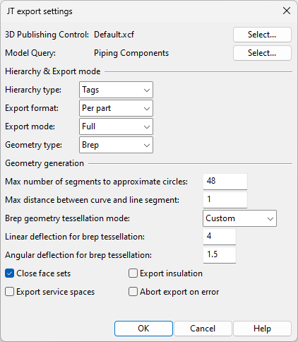
In the "JT export settings" dialog you can specify settings for exporting 3D model objects in the JT format.
- 3D Publishing Control – Specifies the publishing control to use. Click Select to choose the publishing control.
- Model Query – Specifies the model query to use for selecting the objects to export. Click Select to choose the query.
Hierarchy & Export mode
-
Hierarchy type – Specifies what defines the hierarchy to use in the JT file.
-
Export format – Specifies whether to export one file or multiple files.
- Per part – Export each part to a separate JT file.
- Monolithic – Export all parts to a single JT file.
-
Export mode – Specifies whether to export all objects or only the changed ones. This is applicable only when exporting each part to a separate file.
- Full – Always export all objects that match the query.
- Update – After the first export only export the changes: new, modified, or deleted objects. Typically this option provides faster exports, but this can depend on the geometry and the number of exported objects.
-
Geometry type – Specifies geometry export type.
- Brep – All geometry will be exported as complete, and the exported data can be used for generation of 2D drawings, for example.
- Polygonset – All geometry will be exported as surfaces. This is typically faster and suitable for use in viewers.
Geometry generation
- Max number of segments to approximate circles – Specifies the maximum number of segments used to approximate circles in primitives exported as face sets.
- Max distance between curve and line segment – Specifies the maximum distance between curve and approximating polyline exported as face sets.
- Brep geometry tessellation mode – Specifies tessellation mode for brep geometry.
Low, Medium, High – Select one of these to apply predefined values for linear deflection and angular deflection.
Custom – Select this to define linear deflection and angular deflection manually.
Linear deflection — Specifies the maximum distance between an imported higher-order surface (such as spline surface, which are typical for Mechanical CAD models) and its triangulated approximation, using a value from 0.5 to 32.
Angular deflection — Specifies the maximum angle between neighboring (approximated) triangles, using a value from 0.5 to 16.
- Close face sets – If selected, primitives exported as face sets have closed ends.
- Export service spaces – If selected, also Service Spaces that are attached to exported objects are included in export.
- Export insulation – If selected, insulation is exported as objects.
- Abort export on error – If selected, problematic object geometry causes export to stop and no output file is generated. If using a Plant Modeller Service Instance for export, a log file by the name <export_filename>.failed_objects.txt is written into the output directory.