Administrating welds
Weld administration consists of the following.
Setting up weld data
- System setup
- Containment setup
- Weld data setup
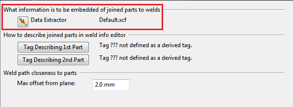
- Description of joined parts in weld info editor
- Wall thickness retrieval vs. doubler plates
- Max offset from plane
System setup
In Plant Modeller, welds are implemented as 3D objects and they belong to a System.
Hull Part Welds in Plant Modeller
Welds that bind Hull parts together are present in Plant Modeller after the hull data has been updated from the Hull application. The System for these welds is Hull Welds (6092). This System is fixed and it is created by the program.
Hull-to-Outfitting Part Welds in Plant Modeller
Systems for welds that bind Hull parts to Outfitting parts can be defined by the project administrator. Welds must be explicitly allowed in the System's properties:
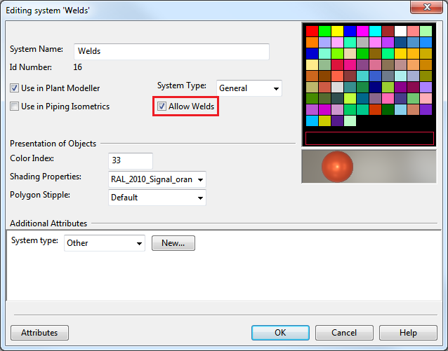
Weld objects can only be assigned to Systems which have the Allow Welds setting enabled.
Containment setup
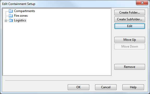
Welds are 3D objects. They are always assigned to weld groups. Weld groups must be created with an association to a logistic structure. This is why you have to have a proper set up for logistic containment in your project or library.
In our example we will associate the weld groups to logistic nodes called blocks. The example is ship-oriented, but you can easily apply the demonstrated workflow to plant-specific weld groups via using a plant-specific logistic structure.
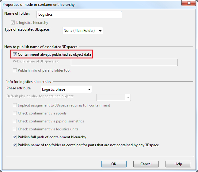
Make sure to have the 3D spaces of blocks in the 3D model. Then select Containment always published as object data for the containment tree node Logistics.
In marine environment the usual logistic containers for weld groups are blocks and outfitting areas.
Weld data setup

Welds join two or more 3D model objects. The picture above shows how data, related to the weld and joined parts, are stored into the weld object.
When queries are made, or lists are extracted, it is mandatory that certain selected data items of the joined objects can also be listed along with the weld data. This is why the system embeds at the weld creation time a selected set of data from the joined parts into the weld object. The system never updates this data and the user can edit it and override the system generated initial values.
Weld Object Data
See the yellow Weld Object Data box in the picture above.
Plant Modeller manages directly a set of weld properties, e.g. the weld number and weld path.
For each weld the system will assign a unique integer attribute, the weld number. Weld numbers cannot be edited by the user. The weld number can be extracted from a weld object via the tag MMT_TAG_WELD_NUMBER (".By). For each weld group a range of weld numbers is assigned. This is by default from 1 to 999. Typically Hull and Outfitting are setup to use a different number range for welds to guarantee the generation of unique numbers inside the same block.
The weld identification for lists and labels is usually composed of several data items and includes the weld number and the weld group name, thus making the identification string unique.
The weld path stores the geometry of the weld seam as a 3D polyline definition with straight line and circular arc segments.
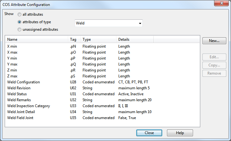
Attributes can be created in COS schema and assigned to the COS object Weld. These attributes can be retrieved in the normal way via referencing their abbreviations.
In our case example the user attributes for welds are:
Joined Part Data, Embedded to the Weld Object
See the pink and cyan boxes in the picture below Weld Data Setup header:
Wall thickness equals to the thickness of the welded object at the weld location. The initial values are extracted by the system, if possible, and embedded into the weld data.
If the joined object references a dimension table, the default value will be set to the value of the first dimension of the quantity type wall thickness. If such quantity type does not exist, then a zero value is set instead.
If the joined object is a CADMATIC Hull object, then the thickness value is extracted as it is published by the Hull module.
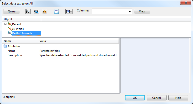
With Data Extractor the project administrator can configure which data of the joined object will be embedded into the weld. The usage of Data Extractor is optional. The Data Extractor to be used in the project can be selected in File > Options > Shared Settings > Welds.
Technically Data Extractor is a 3D Publishing Control COS object.
An example Data Extractor supporting our use case:
/*
Publish data of parts in weld.
*/
ver 500;;
/* No hierarchies */
< hierarchies;;
> hierarchies;;
/* Hull parts modeled as pieces of equipment */
obt 1; abr .sp;; /* thickness */
obt 1; abr .sq;; /* material */
obt 1; abr !0A;; /* NCH_Thickness */
/* STANDARD COMPONENT */
obt 2; abr ST; cpc 1;;
obt 2; abr MC; cpc 1;;
/* STRUCTURAL */
obt 4; abr GRA;;
obt 4; abr MC; cpc 1;;
/* BEAM */
obt 5; abr ST; cpc 1;;
obt 5; abr MC; cpc 1;;
/* HVAC */
obt 6; abr ST; cpc 1;;
obt 6; abr MC; cpc 1;;
/* CABLE TRAY */
obt 7; abr ST; cpc 1;;
obt 7; abr MC; cpc 1;;
/*PIPE */
obt 9; abr ST; cpc 1;;
obt 9; abr MC; cpc 1;;
Sometimes the generated lists should print combined or derived information and not directly the attributes or embedded data items.
This can be implemented via adding a custom script in the project setup to post process the weld object data on any query.
A script with the fixed name: PmWeldCustomization will be automatically called by the system, when such a script exists. It publishes derived tags of the weld data. Derived tags can be accessed in the normal way via tag abbreviations by Model Queries, scripts and ICGDs.
PmWeldCustomization.mac should be added as a "Script Source" type object into the project or library COS database:
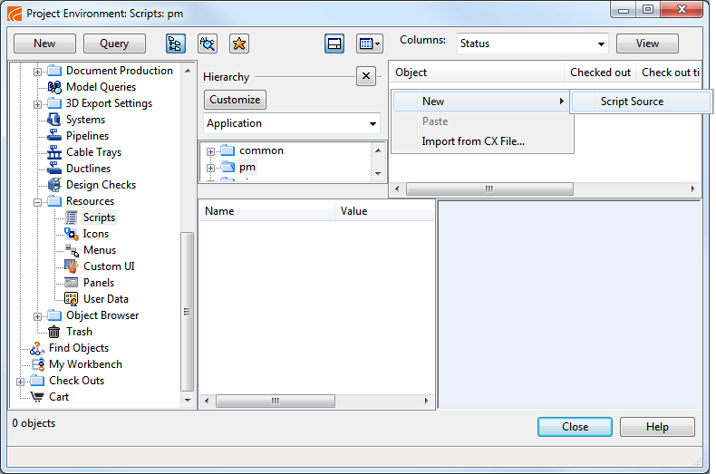
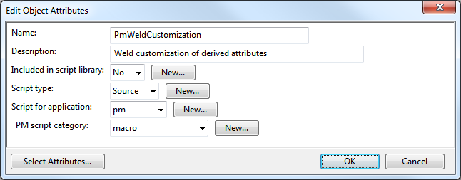
Notice: do not use the extension ".mac" in the name.
The range of the valid derived tag names in the customization is restricted to the contiguous set of three character tag names from "_D?" where ? takes a value from 0–9 in the numeric range or A–Z in the printable character range.
The example PmWeldCustomization script:
#include "include/pm_core_tags.h"
#include "include/pm.h"
#include "include/dmutil.h"

/*
    Get material of a part, associated with the weld.
    The part can be either a hull object or an outfitting object.
    The tag value, defining the material, is extracted per type.
*/
get_material_part_material(part_handle)
{
    /* Case: object is a hull object */
    hull_mc = PM_GET_OBJDATA(part_handle, 0, ".sq"); /* Hull object material  */
    if (!ISINT(hull_mc))
        return hull_mc;

    /* Case: object is an oufitting object */

    /* get Datamatic PID */
    pid = PM_GET_OBJDATA(part_handle, 0, "pid");
    if (ISINT(pid))
        return "";

    /* get the "material" property of the Catalog Part COS object */
    mc = DM_PARTID_DATA(pid, "MC");
    if (ISINT(mc))
        return "";

    return mc;
}

/*
    Define the derived tags that are going to be used for Welds.

    The tag range for derived tags is: _D0 - _Dz
    The last character can be 0 - 9, A - Z or a - z.

    Records here use the same tags as tag files in
    pmsXX/pm/english/tags.
*/
GetUsedTags()
{
    rec_list = A_ALLOC(7);

    rec = DM_INIT_TAGREC();
    DM_SET_TAGVAL(rec, "abr", "_D0");
    DM_SET_TAGVAL(rec, "dsc", "Weld identifier");
    DM_SET_TAGVAL(rec, "typ", "6");
    DM_SET_TAGVAL(rec, "len", "20");
    DM_SET_TAGVAL(rec, "dle", "20");
    A_PUT(rec_list, 0, rec);

    rec = DM_INIT_TAGREC();
    DM_SET_TAGVAL(rec, "abr", "_D1");
    DM_SET_TAGVAL(rec, "dsc", "Part 1 name");
    DM_SET_TAGVAL(rec, "typ", "6");
    DM_SET_TAGVAL(rec, "len", "40");
    DM_SET_TAGVAL(rec, "dle", "40");
    A_PUT(rec_list, 1, rec);

    rec = DM_INIT_TAGREC();
    DM_SET_TAGVAL(rec, "abr", "_D2");
    DM_SET_TAGVAL(rec, "dsc", "Part 1 Grade");
    DM_SET_TAGVAL(rec, "typ", "6");
    DM_SET_TAGVAL(rec, "len", "40");
    DM_SET_TAGVAL(rec, "dle", "40");
    A_PUT(rec_list, 2, rec);

    rec = DM_INIT_TAGREC();
    DM_SET_TAGVAL(rec, "abr", "_D3");
    DM_SET_TAGVAL(rec, "dsc", "Part 2 name");
    DM_SET_TAGVAL(rec, "typ", "6");
    DM_SET_TAGVAL(rec, "len", "40");
    DM_SET_TAGVAL(rec, "dle", "40");
    A_PUT(rec_list, 3, rec);

    rec = DM_INIT_TAGREC();
    DM_SET_TAGVAL(rec, "abr", "_D4");
    DM_SET_TAGVAL(rec, "dsc", "Part 2 Grade");
    DM_SET_TAGVAL(rec, "typ", "6");
    DM_SET_TAGVAL(rec, "len", "40");
    DM_SET_TAGVAL(rec, "dle", "40");
    A_PUT(rec_list, 4, rec);

    rec = DM_INIT_TAGREC();
    DM_SET_TAGVAL(rec, "abr", "_D5");
    DM_SET_TAGVAL(rec, "dsc", "Part 1 thickness");
    DM_SET_TAGVAL(rec, "typ", "2");
    DM_SET_TAGVAL(rec, "qid", "1");
    DM_SET_TAGVAL(rec, "min", "0.0");
    DM_SET_TAGVAL(rec, "max", "9999.0");
    A_PUT(rec_list, 5, rec);

    rec = DM_INIT_TAGREC();
    DM_SET_TAGVAL(rec, "abr", "_D6");
    DM_SET_TAGVAL(rec, "dsc", "Part 2 thickness");
    DM_SET_TAGVAL(rec, "typ", "2");
    DM_SET_TAGVAL(rec, "qid", "1");
    DM_SET_TAGVAL(rec, "min", "0.0");
    DM_SET_TAGVAL(rec, "max", "9999.0");
    A_PUT(rec_list, 6, rec);


    return rec_list;
}

/*
    Construct the record of derived tags for the given weld.
    The tags will publish data, derived from the weld object and the welded objects (parts).

    In this setup the following derived tags will be published:

    _D0:    Weld identifier:
    In this setup the weld identifier will be constructed like this:

            C-U1001-0001

            <PenetratioType>-U<WeldGroupName>-<WeldNumber>

            PenetrationType: A single character, based on the code value of the attribute "Weld Configuration" (U28 in this schema):
                0: C  (Full penetration / T Joint)
                1: C  (Full Penetration / Butt Joint)
                2: P  (Partial Penetration / T Joint)
                3: P  (Partial Penetration / Butt Joint)
                4: F  (Fillet Weld / T Joint)

                U           Fixed character

                WeldGroupName  (derived from the block name)

                WeldNumber  The weld number with four digits


    _D1     Part 1 name:
                            Part names will be constructed:
                            "Part " + objid

    _D2     Part 1 grade:
                            Part grades will be constructed:
                            Hull object:    Value of the attribute NCH_Material ("!04")
                            Outfitting object: Value of Catalog Part attribute: Material ("MC")

    _D3     Part 2 name:
    _D4     Part 2 grade:


    Input Arguments:
    weld_handle:    Object handle of the weld object.

    Output Arguments:
    mrec:           Tag record handle. Stores the values of the derived tags.

    Return values:
        On success: int 0
        On error:   int -1
*/
AdditionalWeldMRecInfo(weld_handle, mrec)
{
    string s_thk;

    /* construct weld id */
    weld_prefix = "?";
    weld_conf = PM_GET_OBJDATA(weld_handle, 0, "U28");
    if (weld_conf != "") {
        if (weld_conf == "0" | weld_conf == "1")
            weld_prefix = "C";
        else if (weld_conf == "2" | weld_conf == "3")
            weld_prefix = "P";
        else if (weld_conf == "4")
            weld_prefix = "F";
    }

    group_name = "<no group>";
    weld_group = PM_GET_OBJECT_GROUP(weld_handle, 54);
    if (!ISINT(weld_group))
        group_name = PM_GET_OBJDATA(weld_group, 0, MMT_TAG_OBJNAME);

    weld_num = PM_GET_OBJDATA(weld_handle, 0, MMT_TAG_WELD_NUMBER);
    if (weld_num == "")
        weld_num = "<no weld number>";


    weld_id = weld_prefix + "-" + group_name + "-" + weld_num;

    DM_SET_TAGVAL(mrec, "_D0", weld_id);

    rec = DM_INIT_TAGREC();
    part_oid = "";
    thickness = 0.0;
    if (PM_GET_WELD_PART_INFO(weld_handle, 1, part_oid, thickness, rec) == 0) {
        objid = PM_OBJID_FROM_COSOID(part_oid);
        DM_SET_TAGVAL(mrec, "_D1", "Part " + objid);

        part_handle = PM_FIND_BY_OBJID(objid);
        if (!ISINT(part_handle)){
            DM_SET_TAGVAL(mrec, "_D2", get_material_part_material(part_handle));
            s_thk = "";
            S_PRINTF(s_thk, "%.1f", thickness);
            DM_SET_TAGVAL(mrec, "_D5", s_thk);
        }
    }

    DM_CLEAR_TAGREC(rec);
    if (PM_GET_WELD_PART_INFO(weld_handle, 2, part_oid, thickness, rec) == 0) {
        objid = PM_OBJID_FROM_COSOID(part_oid);
        DM_SET_TAGVAL(mrec, "_D3", "Part " + objid);

        part_handle = PM_FIND_BY_OBJID(objid);
        if (!ISINT(part_handle)){
            DM_SET_TAGVAL(mrec, "_D4", get_material_part_material(part_handle));
            s_thk = "";
            S_PRINTF(s_thk, "%.1f", thickness);
            DM_SET_TAGVAL(mrec, "_D6", s_thk);
        }
    }

    DM_FREE_TAGREC(rec);

    return 0;
}
Description of joined parts in weld info editor
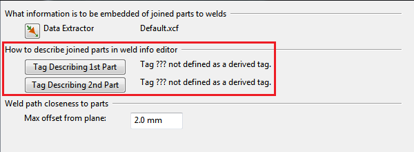
Define the tag describing the first part:
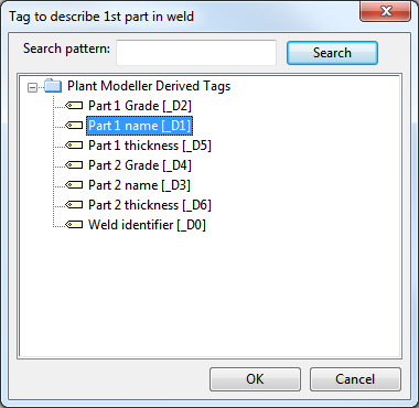
and correspondingly the tag describing the 2nd part.
Note: To see these tags in "Plant Modeller Derived Tags", the PmWeldCustomization script must exist in the system and the Plant Modeller application must be closed and restarted to register the tags, as introduced in PmWeldCustomization.
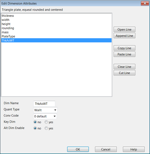
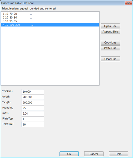
Wall thickness retrieval vs. doubler plates
When using doubler plates, it is desirable that the system can retrieve the value of wall thickness from the joined object and store it to the embedded data of the joined part in the weld object.
Dimension tables of doubler plates are often defined so that the dimension table validator does not allow the user to change the quantity type of the first length dimension to wall thickness. In that case simply add one more dimension to the dimension table and set its quantity type to be wall thickness and assign the thickness value.
Max offset from plane
Maximum offset from plane can be set in File > Options > Shared Settings > Welds.
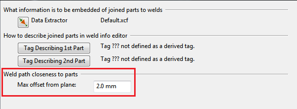
This setting defines for the weld creation wizards the maximum offset from the welding plane when automatically generating the weld path geometry.
Setting up weld drawings
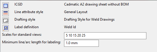
For weld drawings and lists the following things need to be set up:
- ICGD
- Line attribute style
- Drafting style
- Label definition
- Scales for standard views
- Minimum line/arc length for labeling
- Weld drawing style
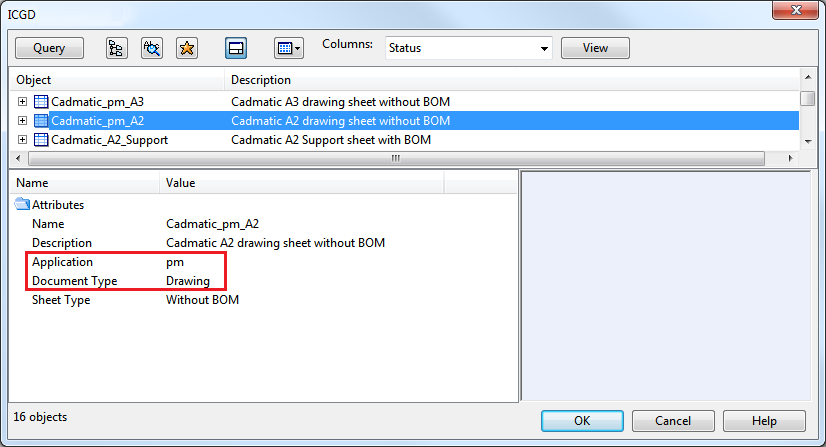
ICGD
An ICGD can be selected if its Application equals to pm and its Document Type equals to drawing.
Line attribute style
In our case example no special needs exist for the line attribute style, and the normal layout drawing views style can be used.
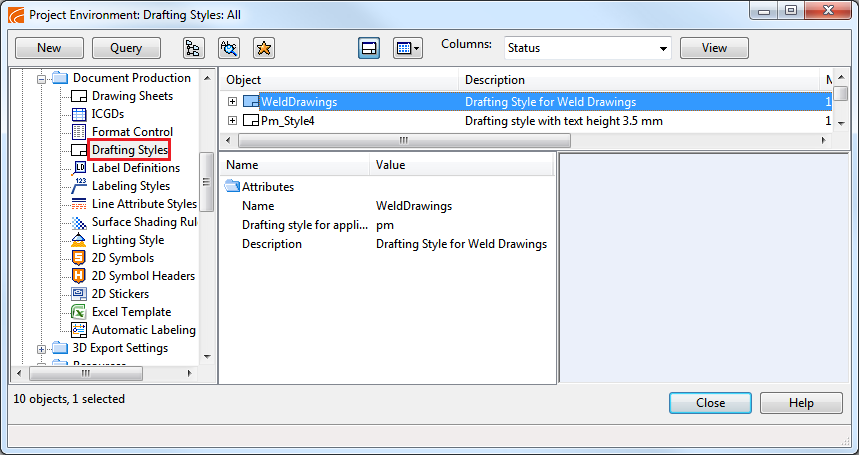
Drafting style
Weld labels can be generated automatically. Due to the automatic labeling the script function CreateTemplateEntitiesForAutomaticAnnotations() needs to be implemented in the selected drafting style.
An example listing of a Drafting Style with weld label settings:
/*
** An example that specifies a drafting style that can be used for views in weld drawings.
**
** This style sets user defaults and also specifies text properties for text entities that
** are automatically placed to views by PlantModeller's Weld Drawing module.
**
** Settings for weld drawings should refer to this style to activate its use with weld drawings.
**
** Original coding by Kari Nylund, October 2015.
**
** Global variables:
**
** -TEXT
**
** Txt_color = int ]0,128[
** Txt_pen = int ]0,256[
** Txt_layer = int ]0,256[
** Txt_type = int >= 0
** Txt_height = float > 0.0
** Txt_width = float > 0.0
** Txt_spacing = float > 0.0
** Txt_slant = float [0.0,90.0]
** Txt_lorg = int ]1,9[
** Txt_dirct = float ]-360.0,360.0[
**
**
** -LINE
**
** Lin_color = int ]0,128[
** Lin_pen = int ]0,256[
** Lin_layer = int ]0,256[
** Lin_type = int >= 0
** Lin_typelen = float ]0.1,1000.0[
** Lin_ends = int ]0,4[
**
**
** -SYMBOL
**
** Sym_color = int ]0,128[
** Sym_pen = int ]0,256[
** Sym_layer = int ]0,256[
** Sym_x_scale = float ]-1000.0,1000.0[
** Sym_y_scale = float ]-1000.0,1000.0[
** Sym_direct = float ]-360.0,360.0[
**
**
** -DIMENSIONLINE
**
** Dim_color = int ]0,128[
** Dim_pen = int ]0,256[
** Dim_layer = int ]0,256[
** Dim_ofsetex = float
** Dim_form = string
** Dim_symheight = float
** Dim_type = int >= 0
** Dim_valdist = float
** Dim_prefix = string "" or text
** Dim_postfix = string "" or text
** Dim_value = string "" or text
** Dim_underline = int ]0,1[
** Dim_txt_type = int >= 0
** Dim_txt_height = float >= 0.0
** Dim_txt_width = float >= 0.0
** Dim_txt_spacing = float >= 0.0
** Dim_ext_line_gap = float >= 0.0
**
**
** -ARCDIMENSIONLINE
**
** ArcDim_ofsetex = float
** ArcDim_form = string
** ArcDim_symheight = float
** ArcDim_valdist = float
** ArcDim_prefix = string "" or text
** ArcDim_postfix = string "" or text
** ArcDim_value = string "" or text
** ArcDim_underline = int ]0,1[
**
**
** -ARC
**
** Arc_color = int ]0,128[
** Arc_pen = int ]0,256[
** Arc_layer = int ]0,256[
**
**
** -HATCH
**
** Hatch_color = int ]0,128[
** Hatch_pen = int ]0,256[
** Hatch_layer = int ]0,256[
** Hatch_style = int >= 0
** Hatch_draw_boundary = int ]0,1[
** Hatch_x_orig = float
** Hatch_y_orig = float
** Hatch_direct = float ]-360.0,360.0[
*/
#include include/init_dw_settings.h
InitPageDwSettings( dw )
{
DW_ACTIVATEVIEW( dw );
return( InitViewDwSettings( dw ));
}
/* This interface is called when we just need to access templates. */
InitViewDwWithTemplateSettings(dw)
{
InitViewDwSettings( dw );
CreateTemplateEntitiesForAutomaticAnnotations();
}
InitViewDwSettings( dw )
{
DW_ACTIVATEVIEW( dw );
/*
** TEXT params
*/
Txt_color = 1 ;
Txt_pen = 1 ;
Txt_layer = 101 ;
Txt_type = 0 ;
Txt_height = 1.5 ;
Txt_width = Txt_height * 0.7 ;
Txt_spacing = Txt_height * 0.15;
Txt_slant = 0.0 ;
Txt_lorg = 5 ;
Txt_dirct = 0.0 ;
/*
** LINE params
*/
Lin_color = 3 ;
Lin_pen = 1 ;
Lin_layer = 102 ;
Lin_type = 1 ;
Lin_typelen = 2.0 ;
Lin_ends = 1 ;
/*
** SYMBOL params
*/
Sym_color = 1 ;
Sym_pen = 1 ;
Sym_layer = 103 ;
Sym_x_scale = 1.0 ;
Sym_y_scale = 1.0 ;
Sym_direct = 0.0 ;
/*
** DIMENSIONLINE params
*/
Dim_color = 3 ;
Dim_pen = 1 ;
Dim_layer = 104 ;
Dim_ofsetex = 1.5 ;
Dim_form = "%Qa" ;
Dim_symheight = Txt_height;
Dim_type = 1 ;
Dim_valdist = 1 ;
Dim_prefix = "" ;
Dim_postfix = "" ;
Dim_value = "" ;
Dim_underline = 0 ;
Dim_txt_type = 0 ;
Dim_txt_height = Txt_height;
Dim_txt_width = Txt_width ;
Dim_txt_spacing = Txt_spacing;
Dim_ext_line_gap= 1.0 ;
/*
** ARCDIMENSIONLINE params
*/
ArcDim_ofsetex = 1.5 ;
ArcDim_form = "%Qa" ;
ArcDim_symheight = 1.5 ;
ArcDim_valdist = 1.15 ;
ArcDim_prefix = "" ;
ArcDim_postfix = "°" ;
ArcDim_value = "" ;
ArcDim_underline = 0 ;
/*
** ARC params
*/
Arc_color = 1 ;
Arc_pen = 1 ;
Arc_layer = 105 ;
/*
** HATCH params
*/
Hatch_color = 1 ;
Hatch_pen = 1 ;
Hatch_layer = 106 ;
Hatch_style = 1 ;
Hatch_draw_boundary = 1 ;
Hatch_x_orig = 0.0 ;
Hatch_y_orig = 0.0 ;
Hatch_direct = 45.0 ;
InitDwSettings( dw );
}
/*
* The following section specifies properties for text entities that are automatically
* placed on views in weld drawings. Key for lookup is the text value in each entity.
* So, don't change the text values while changing other properties.
*/
CreateTemplateEntitiesForAutomaticAnnotations()
{
/* First set fixed properties */
DW_OWNER(0);
DW_LABEL( 0 );
DW_TCENTER( 5 ); /* local origin will be set by application */
DW_TDIRECT( 0 ); /* also local text direction will be overridden if needed. */
/*
* Properties for texts that show weld number label. Notice that there is a separate setting that specifies
* label definition that specifies contents for the label and text type for it. Usually type is 11 --> text in box with
* reference line.
*/
DW_DRWATTR(101, 1, 1); /* layer, color and index to line width table, here we use thinnest line*/
DW_TSLANT( 0 ); /* text slant, degrees from vertical */
DW_TSIZE(2.5,1.8,0.5); /* size of text as millimeters on paper, height, width, spacing */
DW_TTYPE( 31997 ); /* hard wired text type for text with reference arrow */
DW_TEXT( "WELD LABEL", 0, 30, 0, 0); /* this text is a template from which all preceding settings will be copied to real weld labels */
/*
* Properties for texts that show view title and its scale.
*/
DW_DRWATTR(101, 1, 3);
DW_TSIZE(4,2.8,.8);
DW_TTYPE( 3 ); /* underlined text */
DW_TEXT( "VIEW TITLE", 0, 20, 0, 0);
DW_DRWATTR(101, 2, 2);
DW_TSLANT( 10 ); /* make look like italics */
DW_TSIZE(3.0,2.1,0.6);
DW_TTYPE( 3 );
DW_TEXT( "VIEW SCALE", 0, 10, 0, 0);
}
Note: In addition to a normal drafting style the drafting style for weld drawings should define the function: CreateTemplateEntitiesForAutomaticAnnotations(). This will be used by the automatic id labeling feature of weld drawings.
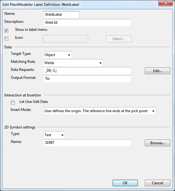
Label definition
The automatic weld labeling uses a "text" type 2D symbol to draw the labels. In this case example the text31997 2D symbol is the one to use for labels.
In weld reports it is possible to list per each weld also the name of the drawing and the name of the view, in which the weld label of the specific weld exists. This will help the reader of the weld list to find the corresponding drawing and the view on it in which the weld is labeled.

Scales for standard views
Plant Modeller creates automatically a plan view for the weld drawing when the drawing is first time accessed via the weld ribbon. It will use one of the scales listed in the weld options.
Minimum line/arc length for labeling
For weld drawings weld labels can be generated automatically. If more than the set minimum length of line/arc from a weld seam is visible in a view then this weld seam can be target for an automatically created weld id label.
Weld drawing style
Define the document style in File > Options > Shared Settings > Documents > Weld Drawing by assigning proper objects.
Setting up weld lists
An Excel report can be exported from the weld tab.
The data extraction uses an ICGD to filter the material stream and an Excel template object to format the data stream to an Excel book of weld data.
Thus the following items need to be set up:
Excel template for weld lists
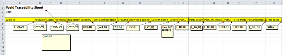
An Excel template actually stores a special Excel workbook in COS. this xlsx file defines the lay-out for data via Excel comments.
Example:
The comment string in the 1st cell of the column Weld Id is {_DO,D}:
This instructs the system to print into this column, under the header cell, the value of the tag “_D0” from the material stream per record, as processed and generated by the ICGD. The type of the cell will be “data” (as defined by the trailing “,D”).
The printing is started at the comment row. As many rows will be printed as there are records with data in the material stream.
An example Excel Template defines the following data columns:
| Column Text Value | Column Comment Value |
|---|---|
|
Weld Id |
{_D0,D} |
|
Revision |
{wrv,D} |
|
Status |
{wst,D} |
|
Remarks |
{wrm,D} |
|
Inspection category |
{wic,D} |
|
Joint configuration |
{wcf,D} |
|
Drawing |
{.C1,D} |
|
Drawing page no. |
{.C2,D} |
|
Section name |
{.C3,D} |
|
Length |
{len,D,DOUBLE} |
|
Part 1 |
{_D1,D} |
|
Part 1 grade |
{_D2,D} |
|
Part 1 thickness |
{_D5,D} |
|
Part 2 |
{_D3,D} |
|
Part 2 grade |
{_D4,D} |
|
Part 2 thickness |
{_D6,D} |
|
Field Joint |
{wfj,D} |
The Excel template for weld list:
Add it as an Excel template object to COS:
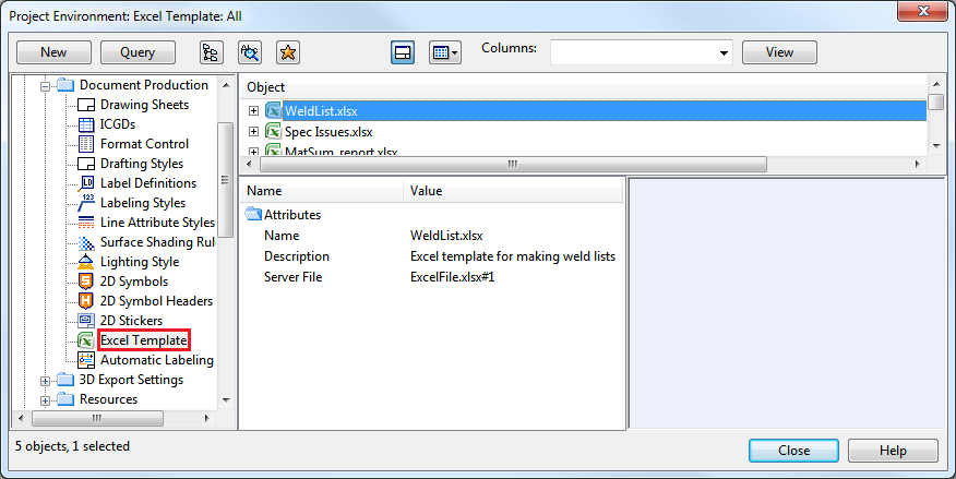
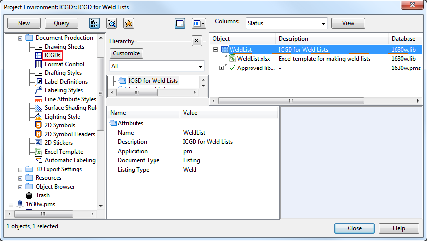
ICGD for weld lists
In our case example we will need an ICGD which extracts the weld data fields to the data stream per weld, and uses an Excel template to output the data into an Excel workbook.
An example, with associated comments:
/*
Example of a weld list
*/
/* HEADER (3 fields) */
;;Excel Weld Object list;
/* Table: Welds */
/* ==================================== */
/* CONTROL BLOCK (4 fields) */
xl; /* Extension of the list */
; /* NO name of drawing sheet */
../xlspool/; /* "printer" spool pathname */
WeldList.xlsx; /* “Format control file”, in this case */
/* a reference to an Excel Template */
/* FIELDS FROM CORPORATE CATALOG (N fields) */
MC; /* Material */
;
/* PRINT HEADER FIELDS */
pro; 1;Project:;; /* Project name */
dat; 1; %s; DAT;; 7;; /* Date */
;
/* PRINT COLUMNS */
_D0; %s; _D0; -1;;; /* Weld Identifier */
wrv; %s; U02; -1;;; /* Weld Revision */
wst; %s; U31;-4;;; /* Weld status (-4 convert */
/* 'enumerated coded' */
/* code values to strings) */
wrm; %s; U32; -1;;; /* Weld Remarks */
wic; %s; U33;-4;;; /* Weld inspection category */
wcf; %s; U34;-4;;; /* Weld configuration */
wfj; %s; U35;-4;;; /* Weld Field Joint */
.C1; %s; .C1; -1;;; /* Weld Drawing */
.C2; %s; .C2; -1;;; /* Weld Drawing Page */
.C3; %s; .C3; -1;;; /* Weld Drawing View */
len; %s; len; 3;20%.0f;; /* Length */
_D1; %s; _D1; -1;;; /* Weld Part 1 name */
_D2; %s; _D2; -1;;; /* Weld Part 1 grade */
_D5; %s; _D5; 1;20%.1f;; /* Weld Part 1 Thickness */
_D3; %s; _D3; -1;;; /* Weld Part 2 name */
_D4; %s; _D3; -1;;; /* Weld Part 2 grade */
_D6; %s; _D6; 1;20%.1f;; /* Weld Part 2 Thickness */
wmt; %s %s; mot;-3;1; /* Modification time hh:mm:ss */
mot;-2;1;; /* Modification date dd.mm.yy */
;
/* SELECTION RULES (each 3 fields) */
obt; 11; 12; /* select welds */
;
/* SORTING RULES (each 2 fields) */
_D0; 2; /* weld id */
;
/* SUMMING RULES */
;;
/* PARAGRAPH TITLE */
; /* NO paragraph title */
; /* NO format */
;
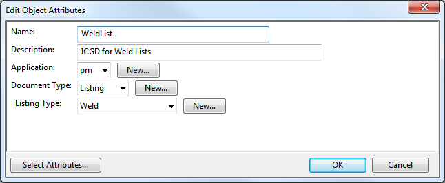
The type of the ICGD must be Listing.
Weld tags in example project
The weld data which can be extracted to labels and reports originates from three tag sets.
Plant Modeller object data: welds
| Name | Tag | Description |
|---|---|---|
|
Weld group name |
.CH |
Name of the weld group. Weld groups are made by some context. Often the context is a block in ship/rig design. |
|
Weld group status |
.CF |
Shows if weld belongs to a weld group (“OK”) or if weld does not belong to a weld group (“Not in a weld group”). |
|
Weld number |
.By |
An integer number, unique per weld inside one weld group. Often used as a part of the weld id. |
|
Weld number status |
.CI |
Shows if weld number for weld can be changed (“Changeable”) or can’t be changed (“Frozen”). |
|
Weld part status |
.CE |
Shows if all welded parts exist in area model (“OK”) or if some of the welded parts don’t exist in the area model (“Missing parts”). |
|
Weld path status |
.CG |
Shows if weld path is OK or if weld path has some problems. |
Plant Modeller object data: weld document
| Name | Tag | Description |
|---|---|---|
| Weld drawing name | .C1 | Name of the weld drawing. In exported lists weld IDs are listed with info about: drawing + drawing page + view name. This combination is naturally needed for finding quickly a specific weld among the hundreds of welds in the group and several pages and many views in the drawing. |
| Weld drawing page number | .C2 | See above |
| Weld drawing view name | .C3 | See above |
Plant Modeller derived tags (configuration: example project)
These tags are defined and the values composed in the project configuration, i.e. in the script source object: PmWeldCustomization:
| Name | Tag | About the value in the use case |
|---|---|---|
|
Weld identifier |
_D0 |
Formed: <PenetrationType>-U<WeldGroupName>-<WeldNumber>. PenetrationType: A single character, based on the code value of the attribute "Weld Configuration" (U28 in this schema):
0: C (Full penetration / T Joint) 1: C (Full Penetration / Butt Joint) 2: P (Partial Penetration / T Joint) 3: P (Partial Penetration / Butt Joint) 4: F (Fillet Weld / T Joint)
U: A fixed character. WeldGroupName: The name of the weld group, in which the weld is a member. WeldNumber: The weld number, printed in this case with four digits. |
|
Part 1 Grade |
_D2 |
Part grades will be constructed: - Hull object: Value of the attribute NCH_Material ("!04") - Outfitting object: Value of Catalog Part attribute: Material ("MC") |
|
Part 1 name |
_D1 |
Part names will be constructed: "Part " + objid” |
|
Part 1 thickness |
_D5 |
Thickness of the material the welded material at the weld. Either a computed or user defined value. |
|
Part 2 Grade |
_D4 |
See Part 1 Grade. |
|
Part 2 name |
_D3 |
See Part 1 name. |
|
Part 2 thickness |
_D6 |
See Part 1 thickness. |