Insert connectors
You can use a pair of connectors to indicate that a pipe run continues in another diagram. That is, you can insert an "Out Connector" where the pipe run ends in the first diagram and an "In Connector" where the pipe run starts again in the other diagram, and link the connectors to each other. The order in which you insert connector symbols into diagrams is not significant. You can add the link while you are inserting the connector symbols, or you manage the linking later, via the Property pane. A "free connector" is a connector symbol that has been inserted into a diagram and saved to COS, but has not been linked to its pair yet. After the linking, the two connectors share the same position ID, and each connector label shows the name of the connected diagram. In a printed diagram the label is visible but the connector symbol itself is not. You can change the color of the connector symbols on your screen in the User Interface settings. You can use the Connected diagram command to jump from one linked connector to the other.
Inserting free connectors
You can insert a connector symbol into a diagram, and then link it to another connector later.
Do the following:
-
In the Template pane, double-click the required connector symbol.
-
Click the pipe run where you want to insert the connector.
-
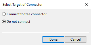
In the Select Target of Connector dialog, select Do not connect and click Done.
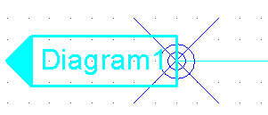
The diagram shows the connector and its empty label.
-
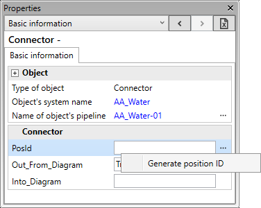
Assign a position ID to the free connector: select the connector in the diagram, open the Properties pane, and type a position ID in the PosId field or generate one from … > Generate position ID.
-
Select File > Save to COS database, and click OK.
Inserting and linking connectors
You can insert a connector symbol into a diagram and link it to an existing free connector in another diagram.
Do the following:
-
In the Template pane, double-click the required connector symbol.
-
Click the pipe run where you want to insert the connector.
-
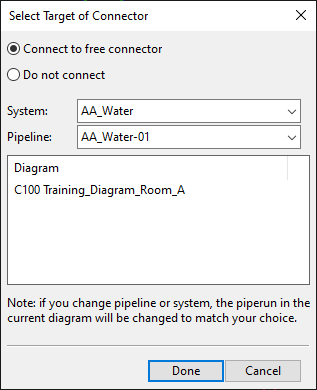
In the Select Target of Connector dialog, do the following:
-
Select Connect to free connector.
-
Select the System and the Pipeline to use for both the connector and the pipe run in the current diagram.
-
The list pane shows the position ID and the diagram of each free connector. Select the target connector from the Diagram list.
-
Click Done.
The diagram shows the connector and its empty label.
-
-
On the Home tab, in the Label group, select Update > All labels. The connector label shows the name of the linked diagram.
-
Select File > Save to COS database, and click OK.
Linking free connectors
You can link two free connectors to each other.
Do the following:
-
Select either of the two connectors.
-
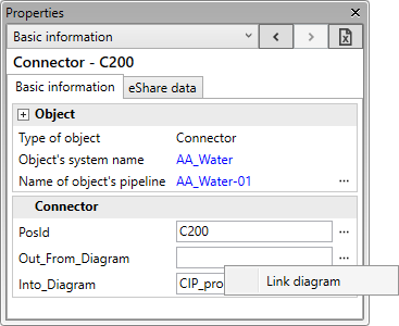
Open the Properties pane.
-
In the Out_From_Diagram field of the In Connector or in the Into_Diagram field of the Out Connector, select … > Link diagram.
-
In the Select Target of Connector dialog, select the target connector, and click Done.
-
On the Home tab, in the Label group, select Update > All labels to update the labels.
-
Select File > Save to COS database, and click OK.
Unlinking connectors
You can unlink connectors that are currently linked to each other.
Do the following:
-
Select either of the two connectors.
-
Open the Properties pane.
-
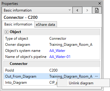
In the Out_From_Diagram or Into_Diagram field, select … > Unlink diagram.
-
On the Home tab, in the Label group, select Update > All labels to update the labels.
-
Select File > Save to COS database, and click OK.