Creating documents
All CADMATIC applications use the same facility to control the generation of documents, drawings or material lists. This topic lists the concepts and terms used with document production.
The application program creates or updates two ASCII files that are associated with the document: a header file (h-file) and a material file (m-file). These files are used to interface the application program to the document processing facility.
Picture below describes the concepts in the context of a Plant Modeller drawing:
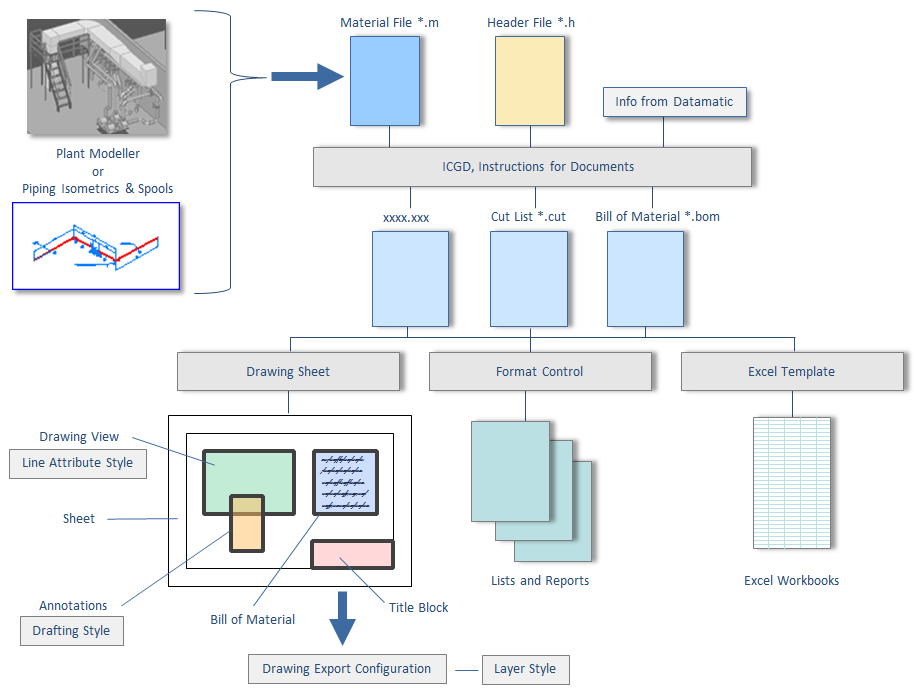
Header File of a Document
The header file (h-file) of a document contains general information about the object that the document represents. For example drawing number, total mass, center of gravity, title, etc. could be stored in a header file. Typically this information is needed in the title block of drawings or in the header fields of printed lists.
Material File of a Document
The material file (m-file) of a document defines the contents of the document from the point of view of material management. This file is taken as input to generate various tables (bill of materials, cut list, summaries, etc.) that will be output to the document.
ICGD - Instructions Controlling Generation of Documents
The processing of bill of materials (BOM) tables associated with a document is controlled by a set of instructions stored in a data set called ICGD. An ICGD specifies what kind of data tables are to be processed from the m-file of the document. Also it specifies whether data tables will be plotted or printed. An ICGD may also define the default drawing sheet to be used for a drawing.
Drawing Sheets
A drawing sheet defines the physical dimensions and general layout of a drawing. It may contain instructions to plot text boxes, symbols, and data tables.
Format Control
Format control objects describe the layout of reports and printable files. Application programs activate report layouts by loading the corresponding format control object. Printing is done to fields and elements which are defined in the page layout. Printable files that are generated in this way are then spooled to a printer after the execution of the program.
Sheet Format File
Sheet Format File includes frames and titles block appearance as 2D symbol. It also defines the position and appearance of the optional Bill of Material (BOM).
Line Attribute Style
Line Attribute Styles define the appearance of the lines (linetype, width, color) of model objects in the drawing views.
Drafting Style
Drafting Style defines the format of annotations for views and page (text, dimension, label, 2D symbol, lines). These annotations can be added manually or automatically. Annotation is placed in view or in page. See Label definitions on how to combine a 2D symbol and attribute information.
Layer Style
Layer Style defines the mapping of systems to layers while exporting. Drawing export configuration is used to define those mappings.
Note: Surface Shading Rules and Lighting Styles are used when publishing an eBrowser model.