CAESAR II export
Overview
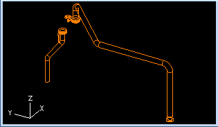
CAESAR II (by Hexagon) is a stress analysis tool for checking pipings. CADMATIC has an additional module for generating CAESAR II neutral files (*.cii files) from Plant Modeller. These neutral files can be imported to CAESAR II for stress analysis. There are also other stress analysis software products such as Bentley AutoPIPE that can load CII files, so the files that CADMATIC generates may possibly be used also in other analysis software.
Setting up Caesar II export
The initial setup should be done by a CADMATIC project administrator. Then, the users just need to select the correct configuration file to run the tool.
COS attributes
Create the following COS attributes, if they do not already exist, and assign them to the COS object types "System", "Pipeline" and "Model Object".
-
Name "Operation Pressure", abbreviation "opP", type String. The default value is 0, the unit is assumed to be kilopascal (kPa).
-
Name "Operation Temperature", abbreviation "opT", type String. The default value is 20, the unit is assumed to be Celsius (C).
-
Name "Corrosion Allowance", abbreviation "coA", type String. The default value is 0, the unit is assumed to be millimeters (mm).
The attribute values are entered as plain text, without any unit identifier. The attribute values only need to be defined at the highest level of the inheritance hierarchy that Plant Modeller uses. That is, set the common attribute values at System level, pipeline-specific attribute values at pipeline level, and object-specific attribute values at object level, as appropriate.
Plant Modeller to CAESAR II configuration file
The configuration file defines following issues:
-
Material mapping between Corporate Part and the CAESAR II material class
-
Branching type between the actual branching in Plant Modeller and branch type in CAESAR II
The file format is the standard CADMATIC tag record file. Currently it needs to be edited with a plain text editor and the configuration is stored in a file (not in a COS configuration object, which needs some attention in a distributed project).
The tags:
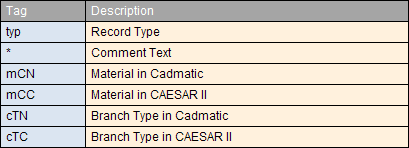
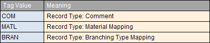
Values of tag ‘typ’:
Values of tag ‘cTN’
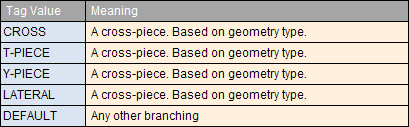
A good selection for the default branching type in CAESAR II is in most cases 2 (stub in).
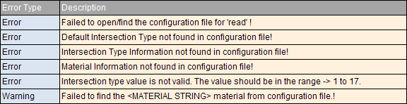
Errors are detected and processing halted in the following cases:
-
Material information not found in configuration file.
-
Intersection type information not found in the configuration file.
-
Default Intersection type not defined.
-
Intersection type value not in the range.
An example configuration file:
typ COM;* --- Start of material mapping information;;
typ MATL;mCN Material undefined;mCC -1;;
typ MATL;mCN St 35;mCC 3;;
typ MATL;mCN St 35 THO;mCC 2;;
typ MATL;mCN SS 2343;mCC 1;;
typ MATL;mCN St 35 NBK;mCC 4;;
typ MATL;mCN A3L;mCC 5;;
typ MATL;mCN OCr18Ni9;mCC 6;;
typ MATL;mCN 20;mCC 7;;
typ MATL;mCN Q235A;mCC 8;;
typ MATL;mCN AISI 316;mCC 9;;
typ MATL;mCN DUCTILE IRON;mCC 10;;
typ MATL;mCN Steel;mCC 11;;
typ MATL;mCN 0Cr18Ni9;mCC 12;;
typ MATL;mCN STAINLESS STEEL;mCC 13;;
typ COM;* --- End of material mapping information;;
typ COM;* --- Start of intersection type mapping information;;
typ BRAN;cTN DEFAULT;cTC 2;;
typ BRAN;cTN CROSS;cTC 3;;
typ BRAN;cTN T-PIECE;cTC 3;;
typ BRAN;cTN Y-PIECE;cTC 3;;
typ BRAN;cTN LATERAL;cTC 3;;
typ COM;* --- End of intersection type mapping information;;
Using the tool
Starting the tool
Start the tool from Plant Modeller menu Model > Export > CAESAR II.
This command is not present in the menu if you did not check the “CAESAR II Link" optional product while installing CADMATIC.
When started for the first time in a Plant Modeller design area the tool requests the user to specify the configuration file. This can be located to any directory. After saving Plant Modeller this path will be stored into the per area application defaults database.
Next the tool: "Export CAESAR II File" pops up.
Selecting what to export
You can enter text to the "Ident" and "Title" records to be attached to the cii file to be generated later.
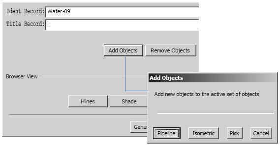
Click Add Objects to add objects to the active set to be generated later into the cii file. A new tool pops up.
-
Click Pipeline to select the contents of a pipeline.
-
Click Isometric to select the contents of an isometric.
-
The name of the isometric group or pipeline will be automatically filled into the "Ident" record if "Pipeline" or "Isometric" was used for selection.
-
Click Pick to pick objects into the cii context.
Note: Notice that Pipeline and Isometric assume that you are working in a design area which encloses all 3D objects in these selected groups. If not, then you are not getting the full contents of the selected group.
Whenever there are objects assigned to the active set the browser view is shown.
-
Click Remove Objects to remove objects from the current selection set. A new tool pops up.
-
Click Pick for picking individual object or All to de-assign all objects from the active selection.
-
Controlling the Browser View
You can use the buttons in the button group "Browser View" to control the browser view:
-
Remove hidden lines
-
Shade the view
-
Change the view direction
Generating cii files
Click Generate File to generate a cii file.
When running the tool for the first time in a design area the tool requests you to select the directory and the base name for the export file. Thereafter the directory path is stored in application defaults database and needs to be defined only if any changes occur.
The tool proposes the contents of the "Ident" field for the base file name, if "Pipeline" or "Isometric" was used for "Add Objects".
If an error or warnings were encountered while generating the cii file, they will be reported. If an error trapped, then processing is immediately halted and no cii file is generated. If warnings encountered, then processing is finished, cii file is generated and the warnings are reported to the user.
More information about Plant Modeller – CAESAR II mapping
About the interface
The processing of Plant Modeller geometry to CAESAR II cii files is done in two stages:
-
Plant Modeller Geometry to CADMATIC Neutral file (the *.psn –file)
-
CADMATIC Neutral File to CAESAR II Neutral File (*.cii)
To understand how components are mapped to CAESAR II it is good to know the following things:
-
CAESAR II does not support valves, flanges, gasket (gaps) directly
-
A "rigid element" in CAESAR II is an element which is considered as an element which will not stretch or bend, but may bring some load (like its weight) to the pipe elements (pipe, bend, reducers..). Thus this is used for representing in CAESAR II many such component types in CADMATIC.
Mapping of CADMATIC components
All the valves, flanges, gasket gaps and other "rigid elements" (from the stress analysis’ point of view) are mapped to the rigid element in CAESAR II.
The visualization of rigid elements in CAESAR II is dependent on:
-
the length
-
the weight
-
the "Outside Diameter" (Od exists in CADMATIC only for pipes!)
-
the "Wall Thickness" (WT exists in CADMATIC only for pipes!)
The weight information for these is passed from Plant Modeller. The outside diameter for flange, valve and "other" rigid elements is taken form the first nominal size value of the CADMATIC component.
Valves
Valves generate one rigid element to CAESAR II.
Flanges, gasket gaps, and their combinations
Flanges and Gasket Gap from Plant Modeller will also be mapped to the rigid element in CAESAR II.
Following combinations of the flanges and gasket gaps are also converted to a single rigid element in the cii file. The weight of the rigid element in CAESAR II file will be the combined weight of all the Flanges.
-
Flange – Flange
-
Flange – Gasket Gap
-
Gasket Gap – Flange
-
Flange – Gasket Gap – Flange
Other rigid elements than valves, flanges, gasket gaps in CAESAR II
If the weight information is not available then add a rigid element with weight "0". This visualizes as a straight line in CAESAR II.
If the weight information is given but the length of this rigid element is less then the "outside diameter" (i.e. in CADMATIC 1’ts nominal size) then add this rigid element as two rigid elements in CAESAR II ("a flange pair").
If the weight information is available and length is more then the "outside diameter" then add one rigid element to CAESAR II (draws it as a valve).
Primary supports
All supports are mapped to "fixed" type supports. Thus the stress analyst needs to assign the proper support function per support.
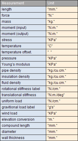
About quantities and units
The link uses units as explained here:
-
Operation pressure = KPa
-
Temperature = C (Celsius degrees)
-
Length = mm
-
Mass of the rigid, valve or flanges = kg.
Below is the table of all the units section currently we are using for our conversion program. (SI (mm)):
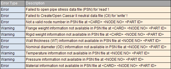
Errors and warnings
While converting the CADMATIC plant model to the CAESAR II then there can be errors or warnings in the conversion process. In case of error the execution will stop immediately and will not proceed. In case of warning the execution can continue. Warning is just like the information to the user about the missing information.
List of errors and warnings:
Configuration File Errors/Warnings
These errors and warnings can be used to fix the issue and add the required information in the CADMATIC plant model and then again execute the converter program. In most of the error messages or warning messages additional information is given to fix the issue like the part id, node number and the type of the element where this error is located. This information is given wherever it is available and applicable. E.g:
Warning:
-
Temperature information not available in PSN file at <NODE NO> <PART ID>
In this case of the user can use the <PART ID> given in the message to search the part in CADMATIC Plant Modeller and then fix the issue in the issue by adding proper values to the COS attributes for this part.
Warning:
-
Failed to find the <MATERIAL STRING> material from configuration file
In this case user should add the mapping of the CADMATIC material <MATERIAL STRING> to the CAESAR II material ID in the configuration file.