CAEPIPE export
You can export piping information to a CAEPIPE model batch file (*.mbf; ASCII format) that can then be imported to CAEPIPE software for stress analysis. Optionally, you can also output a DWG or PDF file that shows the exported geometry.
CAEPIPE by SST Systems, Inc. performs linear and non-linear static and dynamic pipe stress calculations for piping systems of any complexity, in any industry. The software determines the structural response of pipe and pipeline systems to various types of loadings and computes stress results in accordance with numerous international codes and standards.
Prerequisites
-
Optionally, open the Messages pane if you want to see information on the model objects you select for export.
Do the following:
-
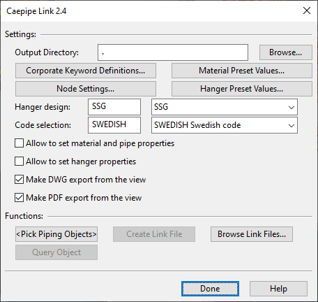
On the Model tab, in the Content group, select Export > CaePipe. The Caepipe Link 2.4 dialog opens.
-
Select the objects to be exported.
 Show/hide details
-
In the Functions section, click Pick Piping Objects.
-
Pick the piping objects from the model. The objects should form a continuous geometry.
If the message pane is open, you can see the number of selected objects and also how many reducers, supports, and flanges are included in the set.
-
Press Enter to accept the selection. The name of the button changes to Pick Pipe Line to indicate that an object set has been defined.
-
-
If you want to see more information on an object you selected for export, click Query Object, pick a model object, and press Enter to open the Object properties dialog for that object.
-
Define the export settings.
Show/hide details
-
Output Directory – Click Browse to select the output directory.
-
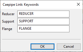
Corporate Keyword Definitions – Opens a dialog for defining keywords that allow the program to recognize reducers, supports, and flanges in the selected pipes. The fields use pattern matching by default—there is no need to use the asterisk character.
-
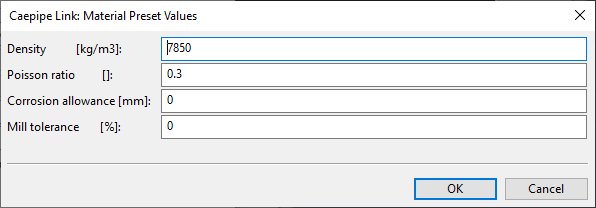
Material Preset Values – Opens a dialog for defining the default material properties of the pipes to be exported. These settings are used for all exported components, unless you select the option that allows the material properties to be defined per component type during the export.
-
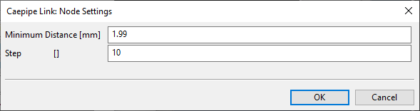
Node Settings – Opens a dialog for defining the minimum distance between the nodes and the increment to use for numbering the nodes.
-
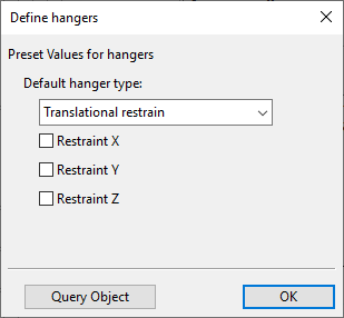
Hanger Preset Values – Opens a dialog for defining the default properties of hanger-type supports. These settings are used for all exported hangers, unless you select the option that allows the properties to be defined per hanger type during the export.
-
Hanger design – Select the hanger type from the drop-down menu.
-
Code selection – Select the piping code from the drop-down menu.
-
Allow to set material and pipe properties – Select this option if you want to define material and pipe properties during the export. Otherwise, default material and pipe properties are used.
-
Allow to set hanger properties – Select this option if you want to define hanger properties during the export. Otherwise, default hanger properties are used.
-
Make DWG export from the view – Select this option to also export the geometry as a DWG file.
-
Make PDF export from the view – Select this option to also export the geometry as a PDF file.
-
-
Export the data.
Show/hide details
-
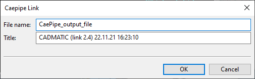
In the Functions section, click Create Link File. The Caepipe Link dialog opens.
-
Define the file name and the title of the file to be generated, and click OK.
-
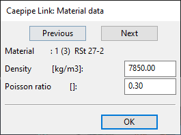
If you are prompted to define material data, define the settings and click OK.
-
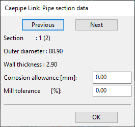
If you are prompted to define section data, define the settings and click OK.
-
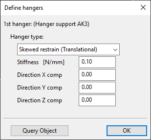
If you are prompted to define hanger data, define the settings and click OK.
The files are exported to the output directory.
-
-
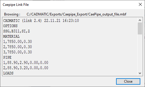
You can click Browse Link Files to open an exported MBF file to a text window.
-
Click Done to exit the export dialog.
Next, the CAEPIPE user can import the generated MBF file via File > Import. We recommend that the CAEPIPE user would have CADMATIC Plant Modeller available, so that they can verify the correctness of the file.
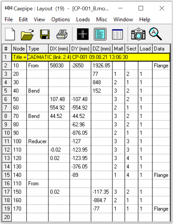
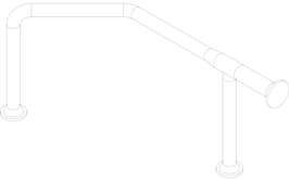
Geometry:
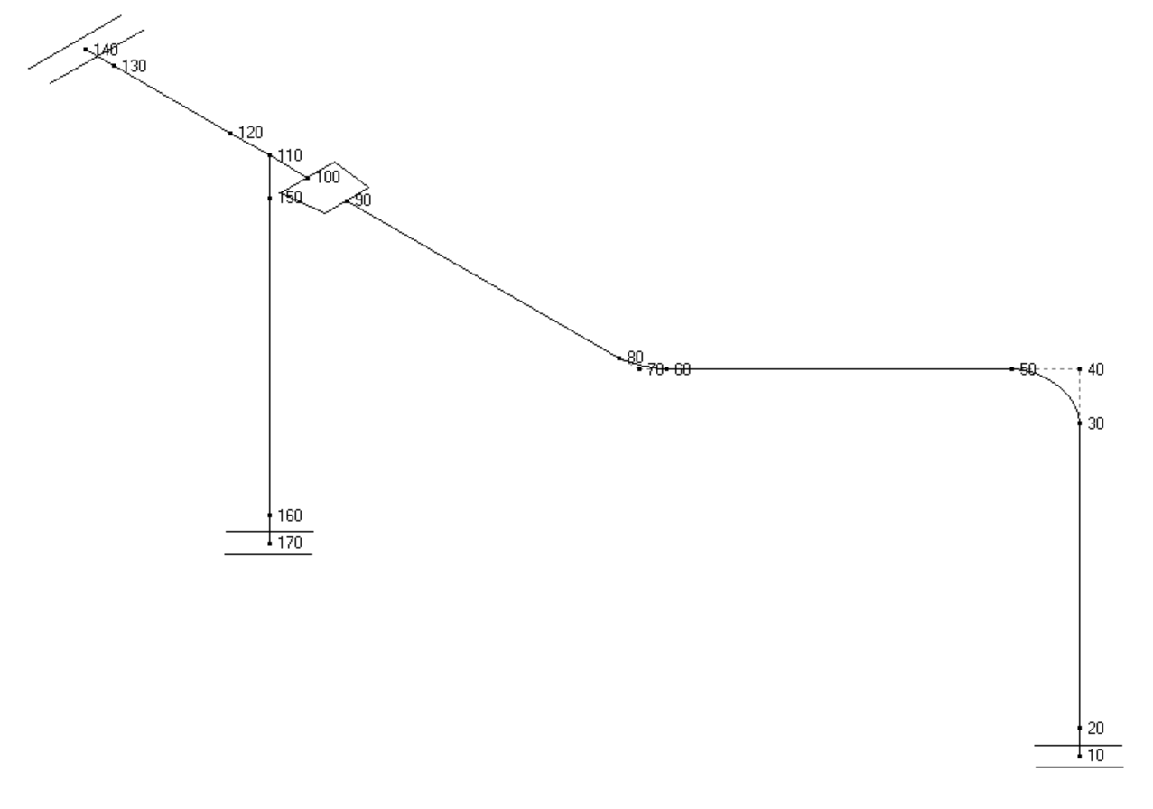
Generated model batch file:
CADMATIC (link 2.4) CP-001 09.08.21 12:58:17
OPTIONS
HGRE,RCC-M,SI,Z
MATERIAL
1,7850.00,0.30
2,7850.00,0.30
3,7850.00,0.30
PIPE
1,114.30,6.02,0.00,0.00
2,114.30,6.02,0.00,0.00
3,141.30,6.55,0.00,0.00
4,141.30,6.55,0.00,0.00
LOADS
1,0,0
LAYOUT
F10,X58030.00,Y-2650.00,Z1926.85,CL=1,FLANGE,WGT=3.6
T20,M1,P2,Z77.00
T30,M2,P1,Z848.00
T40,M3,P2,KI,B152.00,Z152.00
T50,X107.48,Y-107.48
T60,M2,P1,X554.92,Y-554.92
T70,M3,P2,KI,B152.00,X44.52,Y-44.52
T80,Y-62.96
T90,M2,P1,Y-876.05
T100,JD,M3,P3,Y-127.00,COD1=114.30,THK1=6.02,OD2=141.30,THK2=6.55
T110,X-0.02,Y-123.95
T120,P4,X0.02,Y-123.95
T130,M2,Y-376.05
T140,M1,Y-89.00,CFLANGE,WGT=5.6
F110
T150,M3,P2,X0.02,Y0.00,Z-117.35
T160,M2,P1,Z-884.70
T170,M1,Z-77.00,CFLANGE,WGT=3.6
Model batch file imported to CAEPIPE software: