Using a sequence of commands in navigation
When you are defining a point in the model, such as the starting point of routing a pipe, you can refer to geometric entities that are closest to the current 3D cursor position to navigate to the required location. You can, for example, go to the nearest vertex or centerline, as described in 3D navigation commands.
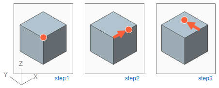
You can perform several navigation commands in a row. In the example below, three navigation commands are used before accepting the point.
-
Step 1: snap to the vertex point by pressing E.
-
Step 2: move 250 mm in X direction by pressing D and then entering the values dx=250, dy=0, dz=0.
-
Step 3: move 200 mm in 90° direction by pressing S and then entering the values Radius=200, Fii=90, Beta=0.
Then press Space to accept the location.
The way in which Plant Modeller determines what is the closest geometric entity depends on whether true 3D proximity (3D hit) is required, or if it is enough to examine the situation as seen in the active view (2D hit).
-
In 3D hit, all three coordinates {x,y,z} are used to find the nearest geometric entity, and you might need to adjust the cursor location in multiple view windows to navigate to the required point.
-
If you have enabled 2D hit or only one view is open, then the depth coordinate is ignored, and the cursor navigates to the first appropriate entity between the viewpoint and the digitized cursor point.
You can toggle the hit mode by pressing Ctrl+2.
-
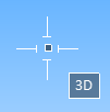
In 3D hit, "3D" displays next to the cursor.
-
In 2D hit, a white circle indicates the current hit distance, and a double frame is drawn around the coordinate axis box.

-
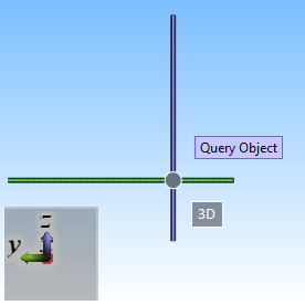
When selecting objects, the cursor is displayed as a cross-hair and a label indicates if 3D hit is on.