Select Model Data to Drawing
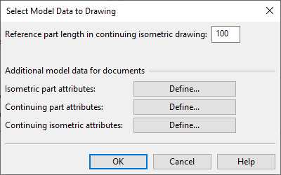
In the Select Model Data to Drawing dialog you can define the following settings.
-
Reference part length in continuing isometric drawing – Specify how many millimeters can be used to show how the piping continues outside the current drawing. These reference parts are drawn with a dashed line type, not dimensioned, and not included in the BOM. If you set the value to zero, then isometric drawings show only those parts that belong to the current drawing.
Additional model data for documents
The program automatically adds mandatory attributes to exported isometric documents. Use the following settings to define which other attributes should be added.
-
Isometric part attributes – Click Define to select which part attributes to add to the piping parts in isometric drawings.
-
Continuing part attributes – Click Define to select which part attributes to add to the reference parts that show how the piping continues from the current drawing.
Note: This setting is ignored if Reference part length in continuing isometric drawing is 0 mm.
-
Continuing isometric attributes – Click Define to select which isometric attributes to add to the reference parts that show how the piping continues from the current drawing.
Note: This setting is ignored if Reference part length in continuing isometric drawing is 0 mm.