2D control
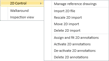
On the Home tab, Views > 2D Control contains the following commands.
Manage reference drawings
A reference drawing is a 2D drawing that is imported from an external file, attached to a work view, drawing view or diagram, and then used as a visual aid by placing 3D design objects, 2D diagram symbols, or 2D annotations on top of the drawing. The format of the imported file can be DWG, DWT, DWF, DWFx, DXF, or DGN, and the files should be stored in a shared folder that is accessible to everybody in the project. The reference drawing can be scaled to the correct size and moved to the appropriate location, and there are various options for changing, for example, the weight and the color of the lines, without affecting the original drawing. If the original drawing is edited, the reference drawing can be updated by reloading the drawing file. If the reference drawing is not needed anymore, it can be hidden from the view or completely removed.
You can import a 2D file as a reference drawing to a Plant Modeller work view.
Do the following:
-
On the Home tab, select Views > 2D Control > Manage reference drawings.
-
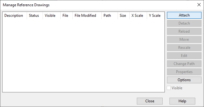
Select the target view from the list, and click OK. The Manage Reference Drawings dialog opens.
-
Attach a 2D drawing to the view:
-
Click Attach.
-
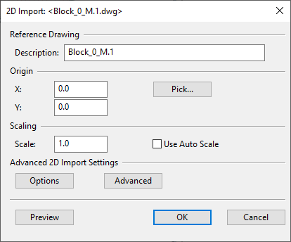
Select the drawing file, and click Open. The 2D Import dialog opens.
-
Define the import settings:
-
Description – Enter a description. This name does not need to be unique.
-
Origin – Set the origin of the 2D file by entering the coordinates or by picking the origin point from the target view.
-
Scale – Define the scale of the reference drawing by entering a specific scaling factor in the format 1/200 or by allowing the program to auto-scale the drawing.
Scaling factor 1 imports the reference drawing using its original dimensions.
-
-
Click Options to define Options for Reference Drawings.
-
Click Advanced to define Common 2D Import Options.
-
Click Preview to preview (and possibly edit) the drawing to be imported.
-
-
Click OK.
After attaching a reference drawing, you can do the following:
-
Move, rescale or hide the drawing.
-
Edit the drawing file.
-
Reload the drawing if the drawing has been changed in the drawing file.
-
Change the path if the drawing file has been moved on the disk.
-
Edit the options.
-
Remove (detach) the imported drawing.
Tip: If you are in Plant Modeller and a reference drawing has been changed on the disk, the Action Center button starts to blink in the Plant Modeller status bar, and you can open the Manage Reference Drawings dialog directly from the Action Center's menu.
Options for Reference Drawings
In the Options For Reference Drawings dialog, you can define options for an individual reference drawing. At the same time, Dxf/Dwg Viewer shows the attached drawing and allows you to select which of the imported objects should be invisible and to define layer options.
In the Options For Reference Drawings dialog, you can define the following options.
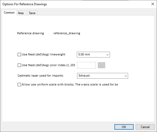
Common
On the Common tab, you can specify the following options:
-
Use fixed (dxf/dwg) lineweight – Select this option to change the lineweight of the reference drawing.
-
Use fixed (dxf/dwg) color index – Select this option to change the line color of the reference drawing.
-
Cadmatic layer used for imports – Select the layer to use for the imported drawing.
-
Allow use uniform scale with blocks… – Select this option to set a uniform scale for the blocks.
Tip: You might want the imported entities to be drawn using thin lines and a neutral color.
Area
On the Area tab, you can specify the following options.
-
Use custom import area – Select this option if you only want a part of the original drawing to be imported as the reference drawing. To define the area, click Start selecting area, and then pick the first and the second corner from the viewer. To see the area you defined, click Draw selected area.
-
Allow move selected objects… – Select this option to move the imported objects by using a base point and a target point that you pick from the viewer.
-
Import text as graphics – Select this option to import texts as graphics.
Save
On the Save tab, you can select which of the following to save:
-
The layer options defined in Dxf/Dwg Viewer
-
The list of invisible objects defined in Dxf/Dwg Viewer
-
Area tab's settings
-
Common tab's settings
Import 2D file
You can import a 2D file into an open or closed view, drawing, or diagram, or even to the symbol editor. The imported 2D file can be in DWG, DXF, DWF, DWT, or CADMATIC 2D DDL format.
Do the following:
-
On the Home tab, select Views > 2D Control > Import 2D file.
-
Select the view from the list, and click OK.
-
Select the file to import, and click Open. The 2D Import dialog opens.
-
Define the import settings:
-
Group Name – Enter a name for the import group. This name has to be unique in this view within 2D imports. The default name is the name of the file, if legal.
-
Origin – Define the origin of the 2D file. You can type the coordinate values or click Pick to pick the point from the view.
-
Scaling – Define the scaling value or select auto-scaling.
-
-
Click Options to change the Common 2D Import Options.
-
Click Preview if you want to see the 2D file you are importing.
-
Click OK to perform the import.
Rescale 2D import
You can use this command to rescale imported 2D files and reference drawings.
Do the following:
-
On the Home tab, select Views > 2D Control > Rescale 2D import.
-
Select the view that contains the entities to be rescaled from the list.
-
Select the 2D import group from the list.
-
Pick a base point for the rescaling.
-
Define the scaling ratio as X and Y values.
Move 2D import
You can use this command to move imported 2D files and reference drawings.
Do the following:
-
On the Home tab, select Views > 2D Control > Move 2D import.
-
Select the view that contains the entities to be moved from the list.
-
Select the 2D import group.
-
Pick a base point for the move.
-
Pick the new location of the base point.
-
Press Enter to accept the new location and click OK.
Delete 2D import
You can use this command to delete imported 2D files and reference drawings.
Do the following:
-
On the Home tab, select Views > 2D Control > Delete 2D import.
-
Select the view that contains the entities to be deleted from the list.
-
Select the 2D import group from the list.
-
Click Yes to accept the deletion.
Assign and fit 2D annotations
Select this command to assign a 2D annotation file (.mg) to a view and scale and position the annotations so that they fit in the view. This is mainly intended for annotations that have been exported from some other CAD system. The "fitting" is needed since native 2D CADMATIC annotations are stored in view coordinates (real world coordinates), whereas the foreign CAD system may handle coordinates in drawing units.
To export 2D annotations from another CAD system, you have to first convert its format to a common format called the "ported 2D file". This conversion is dependent on the particular CAD system.
First you are prompted to select the view to which to fit the 2D file. 2D annotations must not be active for this view. Also, existing annotations for the view will be overwritten.
Then, you are requested to select the 2D file. At this stage, the program copies the 2D file into the directory MMT_VIEWDIR under the name #view.mg, where view is the name of the 3D view. Plant Modeller sets the initial scaling and positioning so that the view fits within the u and v limits of the view and displays the contents of the 2D annotations file.
Next, you are prompted to specify the endpoints of a reference line and its true length. These are used to determine the required scaling. To do this, you must know the true length of some 2D line.
When the above three input events are completed, the program erases 2D annotations from the display, scales the points in the 2D view, and redraws the 2D annotations. Now the 3D view and its 2D annotations should match in scale.
Finally, the program prompts you to specify two points: a reference point and its true position. From these two points the program computes a delta vector that needs to be applied to the 2D points to move them so that they match the 3D view. When the points are given, the 2D annotations are erased from the display, 2D points are translated, and the view displays the final 2D annotations.
Activate 2D annotations
Select this command to activate all 2D annotations in a view. This makes it possible to refer to 2D lines and vertices in POINT, DIR, and PLANE functions.
After you have selected the view, the program dumps the contents of the 2D annotation file to the screen where the view is currently displayed.
De-activate 2D annotations
Select this command to deactivate all 2D annotations in a view. After this, the 2D objects are no longer available as references, but they remain visible until the view is regenerated.
Delete 2D annotations
Select this command to delete all 2D annotations from a view.
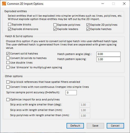
Common 2D Import Options
In the Common 2D Import Options dialog, you can define options that are common to shared by different kinds of 2D file imports.