Isometric drawing
In this exercise, you create an Isometric Drawing one pipeline at a time. The first step is to create an Isometric Group of a pipeline, because an isometric drawing is generated via an isometric group.
Although using one pipeline in an Isometric Group is a common method when creating Isometric Drawings, the other method is to create an Isometric Group of several piping objects selected from several systems.
Modify the options
Do the following:
-
Select Documents > Piping Isometrics.
-
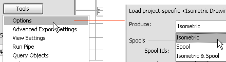
In the Piping Isometrics dialog, select Tools > Options.
-
For Produce, select Isometric.
-
Click OK.
Select the system
Do the following:
-
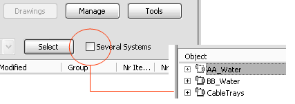
In the Piping Isometrics dialog, clear the checkbox for Several Systems if it is selected.
-
Click Select if the list of systems is empty.
-
Select the system according to the area you are working with.
In this exercise, select the system AA_Water.
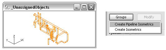
Create an isometric group
The _UnassignedObjects dialog shows the pipelines which are not used in an Isometric Group. A pipeline can be a member of only one isometric group.
Do the following:
-
Select Groups > Create isometrics via containment, system and pipeline.
-
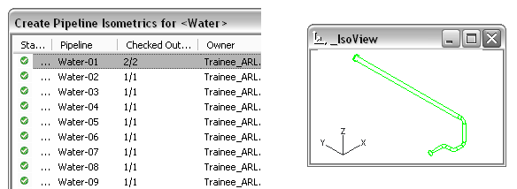
In the Create Pipeline Isometrics for [name of the system], select one of the pipelines.
-
In the _IsoView dialog, verify that you selected the correct pipeline.
-
Click OK to create an Isometric Group of the selected pipeline.
Create an isometric drawing
Do the following:
-
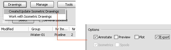
In the Piping Isometrics dialog, Select Drawings > Create isometric/spool drawings.
-
Select the only item on the list.
-
Below Options, select Annotate and Export.
-
Annotate adds labels, symbols, dimensions, and so on, according to the Automatic Annotation Settings.
-
Export creates an additional export file (.pdf, .dwg, .dxf, and so on), according to the Drawing Export settings.
-
-
Click OK.
You have now created an isometric drawing of a pipeline.