Create geometric model (GDL)
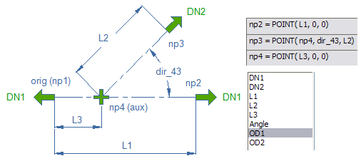
Next you will create the geometry for lateral using template so that the parameters DN1, DN2, L1, L2, L3 and Angle and nodes orig, np2, np3 and np4 are predefined in Component Modeller for you. In addition you will add parameters OD1 and OD2 as outside diameters.
Note: Additional parameters Wall and Mass are added later in Dimension Table.
In the picture below you can see the definitions of node points and all the parameters added in Component Modeller. Parameters OD1 and OD2 are added manually.
Creating a geometric model
Do the following:
-
In Project Environment browse item Components / Catalog Parts / Geometry.
-
Click New > GDL for standard part.
-
Select attributes for geometric model (at least the Description = Lateral_Example).
-
Select geometry type 9 DM_GT_LATERAL. Check “Use template” option.
-
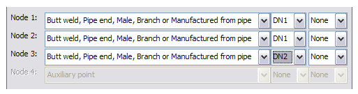
Set connection data: two nominal sizes.
-
Nodes 1 and 2 use DN1 and node 3 uses DN2 as nominal size.
-
Add parameters OD1=168.3 and OD2=114.3 as outside diameters.
-
Set other parameters: DN1=150, DN2=100, L1=250, L2=200, L3=100, Angle=45
Note: Parameters DN1, DN2, L1, L2, L3 and Angle are added automatically when templates are used.
-
Insert cylinder; 1st point at the origin (np1), stretch to the node np2.
-
Use command Scale Shape to set the outside diameter (actually radius) to OD1/2.
-
Insert aligned cylinder; 1st point at np4 and stretch to the node np3.
-
Use command Scale Shape to set the outside diameter (actually radius) to OD2/2.
-
Save the component model and exit to Project Environment.