Ladder, type A, caged, JSL
Construction settings
-
Material for stringers (1)
Valid beam classes for stringers: RHS, Flat
-
Material for rungs (2)
Valid beam classes for rungs: SQ
-
Material for legs (3)
Valid beam classes for legs: L, RHS, Flat
-
Material for cage hoops (4)
Valid beam classes for cage hoops: RHS, Flat
-
Material for cage bars (5)
Valid beam classes for cage bars: RHS, Flat
-
Doubler plate for flat bar (6)
-
Doubler plate for L bar (6)
-
System for passage
-
Minimum platform height to require safety cage
If the height from lower platform to upper platform exceeds the minimum platform height to require safety cage then safety cage is modeled. Otherwise, ladder is modeled without the safety cage.
-
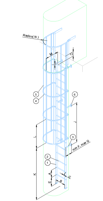
Rise height (vertical distance between the center lines of rungs) (A)
-
Rung width (B)
-
Rung extension width (C)
-
Distance of the highest rung to the upper platform level (D)
-
Max. height of the lowest rung from the floor level (E)
-
Minimum distance from the wall to the center line of the stringers (F)
-
Maximum distance from the wall to the center line of the stringers (G)
-
Vertical distance from the center line of the lowest rung to the lower ends of the stringers (H)
(H) is used only when stiffener connection type is selected during modeling.
-
Vertical distance from the center line of the highest rung to the higher ends of the stringers (I)
-
Max. vertical distance between the leg center lines (J)
-
Distance from the lower end of stringers to safety cage's lowest hoop (K)
-
Maximum spacing between hoops (L)
-
Distance from the center of the rung to the center of safety cage's curve (M)
-
Radius of the safety cage curve (N)
Inserting the unit
-
Select the System.
-
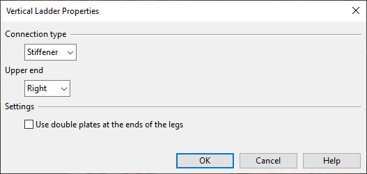
Define the properties.
-
Connection type can be "Stiffener" or "Deck".
In stiffeners, connection type value (H) is used to determine where the stringers end.
Deck connection is connected directly to the defined lower platform with a doubling plate.
-
Upper end can be modeled to right, left or center.
-
Use double plates at the ends of the legs adds double plates to the ends of the legs. This can be adjusted after selecting the points and directions for the ladder.
-
-
Select points and directions.
-
Define the legs.
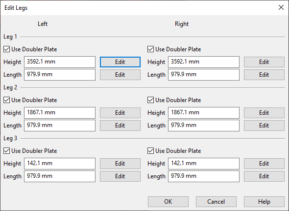
Edit Legs dialog enables the user to edit the height and length of each leg by typing the value or by clicking the Edit button to point the height or length from the model. Usage of doubling plates can be controlled for each leg individually by selecting "Use Doubler Plate".
-
Select a name for the structural unit.
Note: Safety cage is modeled only if the ladder's total height exceeds 4000 mm.