Specification setup for duct parts
In the Project Environment dialog, the project administrator can configure the use of duct parts in the project.
Functional codes for duct parts
In [project] > Configuration > Common, the Functional codes configuration object is used to define functional codes. Each functional code represents a particular duct part type, such as the functional code for duct valves, or the functional code for rectangular-to-round transitions.
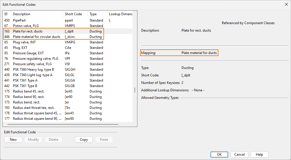
When creating a new functional code for duct parts, first you must select the option To be used in ducting specifications. This displays the additional options Duct part design rule and Part using range lookup; selecting either of these options adds the opening bracket character "[" to the Short code field (to indicate that the Short Code is related to ducting) and disables the Number of spec keysizes setting (to indicate that the functional code represents a range of part sizes rather than a single size).

Note that there is one predefined functional code for rectangular ducts ([_dplt) and another one for circular ducts ([dcirc) made of plate materials. You cannot create additional functional codes for ducts made of plate materials, which means that within a given specification the rectangular or circular ducts can only utilize either thin or thick plates, but not both at the same time.
For general information, see Functional codes.
Component classes for duct parts
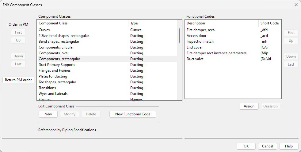
In [project] > Configuration > Common, the Component classes configuration object is used to map each functional code (via its Short Code) to a suitable component class. The component classes form a higher-level hierarchy that enables filtering of duct part types in selection dialogs.
For general information, see Component classes.
Ducting specifications
In [project] > Specifications > Ducting Specifications, a ducting specification defines which duct parts can be used in the ductlines that use the given specification. A ducting specification can include these types of parts:
-
Straight ducts
- Rectangular
- Flat oval
- Circular
-
Duct parts built from plate materials, such as curves and transitions. Their shape is derived from an internal shape code and parameters.
-
Industrially manufactured parts. For example, flat oval segment curves and fire dampers are standard components modeled using Component Modeller.
Note: This classification aims to map to the way parts are manufactured, either in prefabrication shops or industrially. The only exception is straight ducts—they are considered to be prefabricated parts when duct spools are made. Flat oval ducts are assumed to be industrially made so their sizes are fixed, whereas those manufactured in prefabrication shops are not.
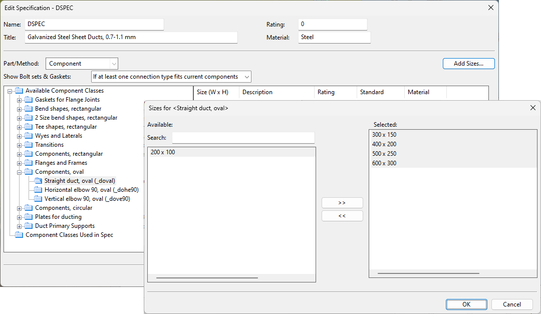
To add a new duct part to a ducting specification, select the part type (functional code) from the Available Component Classes list, and then click Add Sizes to select which part sizes to include to this specification. This will first open an object browser dialog for selecting the required part, and then a dialog for selecting the required part sizes.
-
If the functional code mapped to the component class uses the 'Real part' option, you are prompted to select the required sizes from the fixed set of sizes defined in the component model.
-
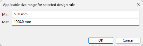
If the functional code mapped to the component class uses the 'Duct part design rule' option, you are prompted to specify a min–max range for the duct parts in the model using either length values or cross-sectional areas—depending on how the duct part design rule has been configured. The value ranges must not overlap.
-
If the functional code mapped to the component class uses the 'Part using range lookup' option, you are prompted to specify a min–max range for the duct parts in the model. The value ranges must not overlap.

-
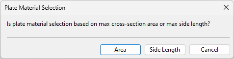
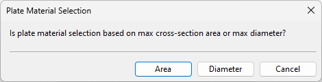
If the functional code mapped to the component class uses plate materials, you are prompted to choose how the plate material is to be selected.
-
For rectangular ducts, the plate material can be looked up from the specification using either the cross-sectional area (required by SOLAS rules) or the longer side length of the duct part.
-
For circular ducts, the plate material can be looked up from the specification using either the cross-sectional area or the diameter of the duct part.
-
-
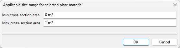
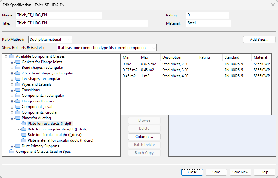
If plate material was chosen to be selected based on area, you are prompted to define the min–max range as area quantities.
Important: Specify the units in which the area is measured, so that proper values are stored. Usually this is square meters (m²).
-
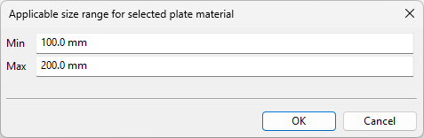
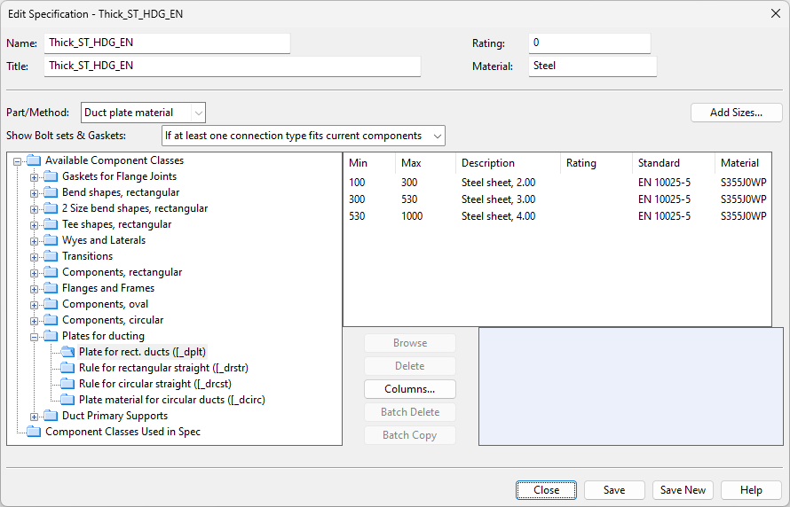
If plate material was chosen to be selected based on side length (rectangular ducts) or diameter (circular ducts), you are prompted to define the min–max range as length quantities.
Further on:
If the specification lookup takes place via the cross-sectional area, then the information for the plate material looks as follows.
If the specification lookup takes place via the side length, then the information for the plate material looks as follows.
Note: If the ducting specification already contains part sizes that use one method for material selection (such as longest cross-section side) and you want to change them to use another method (such as cross-section area), then first you need to delete the existing part size entries. After this, adding new part sizes will prompt you to select the method again.