Isometric Drawing Symbols
Components that are allowed to be exported into isometric drawings can display a specific isometric drawing symbol. The symbol to use is normally selected in the dimension table of the component, but it is also possible to override it in the catalog part.
You can see the existing isometric drawing symbols and create new ones as follows:
-
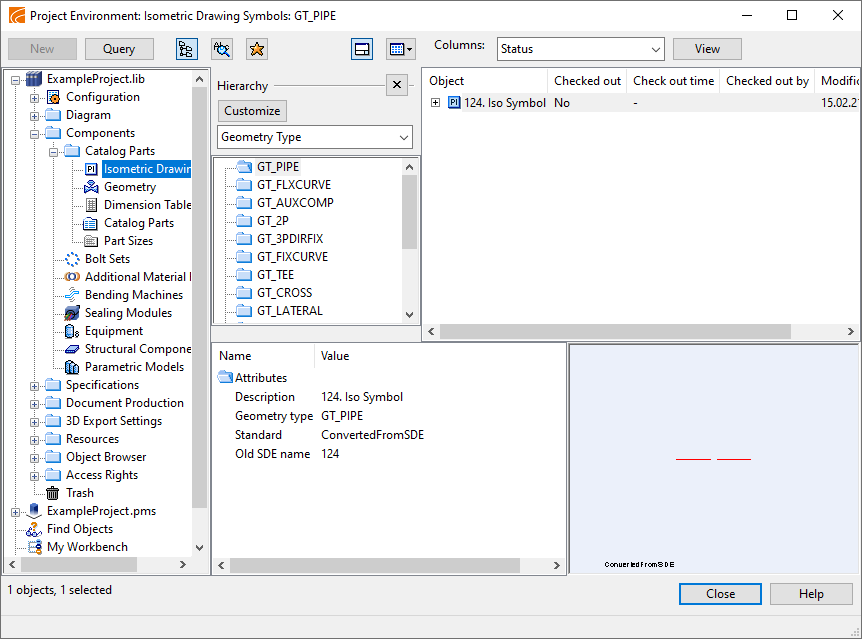
In the Project Environment dialog, browse to [library or project] > Components > Catalog Parts > Isometric Drawing Symbols.
-
In the Piping Isometrics & Spools application's Settings menu, select Symbols and then click Manage Isometric Drawing Symbols.
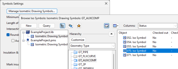
In the browser views, the symbols are listed according to their Geometry Type.
Note that the isometric drawing symbol is fixed for the following components:
|
Symbol |
Geometry type |
Description |
|
|---|---|---|---|
|
Pipe |
1 |
DM_GT_PIPE |
Straight pipe parts |
|
Elbow |
2 |
DM_GT_FLXCURVE |
Elbows or bends |
|
Return pipe |
12 |
DM_GT_RETURN |
Return pipes |
|
Y piece |
13 |
DM_GT_YPIECE |
Y-pieces |
|
No iso symbol |
15 |
DM_GT_FLEXCOMP |
Invisible connection components |