 Point
Point
This is a powerful command that allows you to redefine a point. All objects that are either directly or indirectly dependent on this point get modified.
A point can be defined in several ways. The tool has a choice item that you use to select how you want to define the point. This selection determines what input items you then use to define the points. For example if you selected to define the point via coordinates then there will be three data entry fields where you enter expressions for each coordinate.
If you have selected a style that uses references to other points or directions then there are buttons to specify these references. The button label shows the name of the current reference. If you have not set any reference then the label is "???". When you press the button a small menu is popped up. This has two items: "Pick" and "Show". Pick will allow you to select a point or a direction for that reference. Point picking starts in graphics mode but you can switch to selecting it by name. Picking a direction always takes place via selecting it by its name.
When you have made the changes then press button 'Done'. Now component modeler will evaluate changes to the model. If it turns out that you modified the point in such a way that some dependent object cannot be evaluated then the tool window will stay up and you have to continue to work with the point.
To redefine a point click Edit > Point. All objects that are either directly or indirectly dependent on this point are modified. The following two figures show what happens when you modify point P2. This works if points at ends of primitives have been created as relative points i.e. P3 depends on P2 and P4 depends on P3.
Use command Component Model > Parameters to set the following parameters:
-
Name: Rad1, Type: Diam, Default Value: 100.
-
Name: Rad2, Type: Diam, Default Value: 60.
-
Name: Rad3, Type: Diam, Default Value: 150.
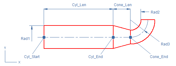
Cylinder:
-
Use command Insert > Primitive > Cylinder.
-
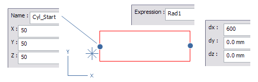
1st point: right-click and select Parameterize (or press O). Name = Cyl_Start and X=Y=Z=50, press space to accept.
-
Stretch: press D (relative displacement) and set dx=600, dy=dz=0, press space to accept.
-
Pick Action: right-click and select Scale Shape to set the cylinder radius.
-
DefRadius: right-click and select Define (or press O) and set expression as Rad1.
-
Press Enter to finish the Cylinder command.
Note: If you want to set the Cyl_End point relative to Cyl_Start point, use predefined parameter Len instead of value 600 as dx value.
-
Use command Edit > Point and click the cylinder end. Name the point as Cyl_End. Notice that the end point is not relative to the start point, the point style is Coordinates.
Note: Use Edit > Point command and right-click for method Select by Name (or press N) to list the named point. Orig is always present as (0,0,0).
Cone:
-
Use command Insert > Primitive > Cone.
-
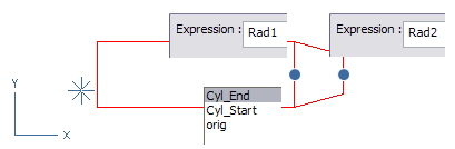
1st point: right-click and use Select by Name command and click the Cyl_End point from the list.
-
DefDistance: right-click and select Define (or press O) command. Set the expression as 150 and click the Var?= button to save the value to variable Cone_Len.
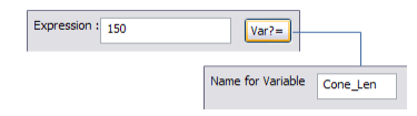
Note: You could also use a predefined parameter or variable as expression.
-
Pick Action: click the start point of the cone, right-click and select Scale Shape.
-
DefRadius: right-click and select Define and set expression as Rad1.
-
Pick Action: click the end point of the cone, right-click and select Scale Shape.
-
DefRadius: right-click and select Define and set expression as Rad2.
-
Press Enter to finish the Cone command.
-
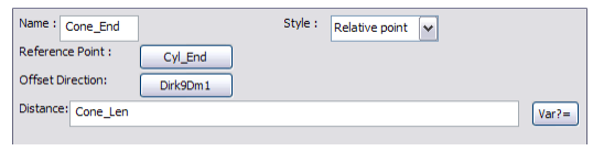
Use command Edit > Point and click the cone end. Name the point as Cone_End. Notice that the end point is relative to the Cyl_End point at the distance Cone_Len.
Toroid:
-
Use command Insert > Primitive > Toroid.
-
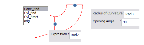
1st point: right-click and use Select by Name command and click the Cone_End point from the list.
-
Dimensions: set the radius of curvature as Rad3 and opening angle to 90.
-
Pick Action: right-click and select Scale Shape.
-
DefRadius: right-click and select Define and set expression as Rad2.
-
Press Enter to finish the Toroid command.
How to modify point
-
Click the point you want to modify. You can select the point also by its name using context menu command Select by Name.
-
Objects that somehow depend on the selected point are highlighted.
-
Modify the definition of the point. You can select the style of the point from the Style pull-down menu. This selection determines the input items to define the points.
-
Make the changes and click OK. Component Modeller will evaluate changes to the model. If you modified the point so that some dependent object can't be evaluated, then the tool window will stay open and you have to continue to work with the point.
Style of the point
-
If you selected the style to be coordinates, there will be three data entry fields where you enter expressions for each coordinate.
-
If you have selected a style that uses references to other points or directions then there are buttons to specify these references. The name of the button tells the name of the current reference. If you haven't set any reference then the label is "???". Click the button to open a menu with two items: Pick and Show. Click Pick to select a point or a direction for that reference. Point picking starts in graphics mode. Click Select By Name or press N to select point by name. Select direction always by its name.