Diagram object types
Armatures
Armatures are diagram objects that belong to a pipeline. A pipe run and the armatures connected to it belong to the same pipeline.
The example project includes the following armature objects:
- Actuators
- Condense traps
- Filters Sight glasses
- Angle valves
- 3-way valves
- Safety valves
- Non-return valves
- Standard valves
- Special devices (like a sprinkler nozzle)
Most of the armatures can be inserted into a line or connected to the end of a pipe run.
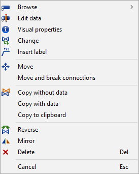
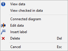
Context menu for armatures:

Equipment
There are two different types of equipment objects:
- Objects inserted into a line, such as pumps and heat exchangers.
- Objects inserted into a free point, such as vessels.
Vessel is a good example of a diagram symbol where the size often needs to be changed.
Context menu for equipment:
Piping objects
Piping objects are different kinds of pipe runs and piping objects, such as reducers and connections, that are inserted onto or into pipe runs.
Line cutting objects, joints
Line cutting objects are specific object types that "cut" the pipe run (like in reality) but do not have position IDs. These include reducers, flanges, steam pockets, etc. There are various such objects in the example project.
These objects are of type "Armature/Symfittings" from the point of view of the database. In some cases, such as with reducers, two nominal sizes should be entered to be able to show the sizes in a label.
Line end components, pipe closing
These objects are like line cutting components, but they are inserted to the ends of pipe runs with the command Connect (P). Typical representatives of this type are blind flanges and welded pressure ends.
These objects are of type "Armature/Symfittings" from the point of view of the database.
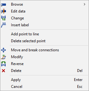
Context menu for pipe runs and circuits:
Instruments
There are two kinds of instrument objects:
- Instrument lines
- Controlling instruments
Instrument lines are similar to pipe run objects. They can either represent measurement or driving signal lines. In the example library, there are some basic types for instrument lines: electrical, pneumatic, hydraulic and capillary lines, and a general instrument line.
Controlling instruments are categorized by their main function: T for temperature, P for pressure, and so on.
When publishing a diagram to the 3D model, any instruments that are not part of a pipeline are published as "Externally Provided P&ID Data" (EPD) objects which the Plant Modeller user can link to 3D model objects as described in Manage integration objects.
Context menu for instruments:
Connectors
Normally, connectors are used to store the information that a pipe run continues from one diagram document to another, although they can also be inserted within a single diagram. Connectors usually form a pair: there is an 'in connector' and an 'out connector', which are linked to each other. A connector that has not been linked yet is a 'free connector'. The example project contains some connector symbols that you can use.
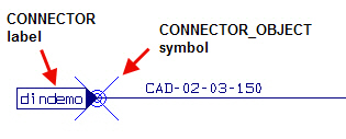
The connector symbol is only displayed on-screen, and not in printed diagrams. Therefore, connectors should have a label that makes the connection evident. In the example project, the connector symbols are configured to display a label that shows the name of the connected diagram.
The project administrator can modify the look of the connector symbol and the connector text. The connector's color can be set via Drafting > Annotate > Symbol > Insert (see Symbol) or via Options (see User Interface).
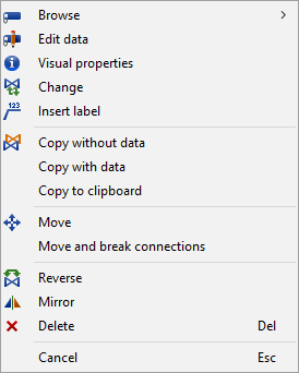
Context menu for connectors:
For more information, see Insert connectors.
Labels
Labels are graphical objects that do not have database records of their own, but usually refer to the record or records of some diagram object. If the contents of the referred field are changed, the label can also be updated to show the new information.
Labels can be simple text labels, or the label text can be written inside some graphical symbol. Any data that a diagram object stores in the database can be shown in a label.
There are some example labels in the library of the example project. The sample labels also include symbols for flow arrow, isolation, tracing, slope marking, z-level, line delimiter, etc.
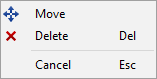
Context menu for labels:
Flexible objects
Flexible objects are diagram symbols that can have their visual appearance updated directly from the database. One such example is a valve with an actuator: the style of both the valve and the actuator changes based on the user's selection, even though the object template remains the same.
Terminators
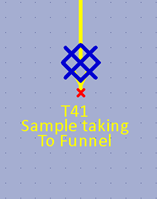
Terminator objects can be used to indicate that a branch or main run purposefully ends with nothing else at the end of the pipe. They can be used to represent gutters, funnels, and sample taking, for example.
The benefits of using terminators include the following:
- Ability to add a label to the end of a pipeline branch.
- Ability to use the information in 3D integration (routing).
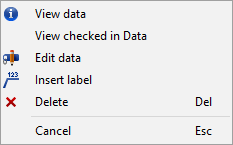
Context menu for terminators:
See Insert terminator.