Insert tab
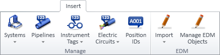
The Insert tab of P&ID contains the following tool groups.
Manage
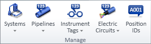
On the Insert tab, the Manage group contains the following tools.
Systems | Pipelines | Instrument Tags | Electric Circuits | Position IDs
Systems

The Systems button contains tools for creating systems and assigning systems to diagram objects.
Define
You can use this command to create new systems.
Do the following:
-
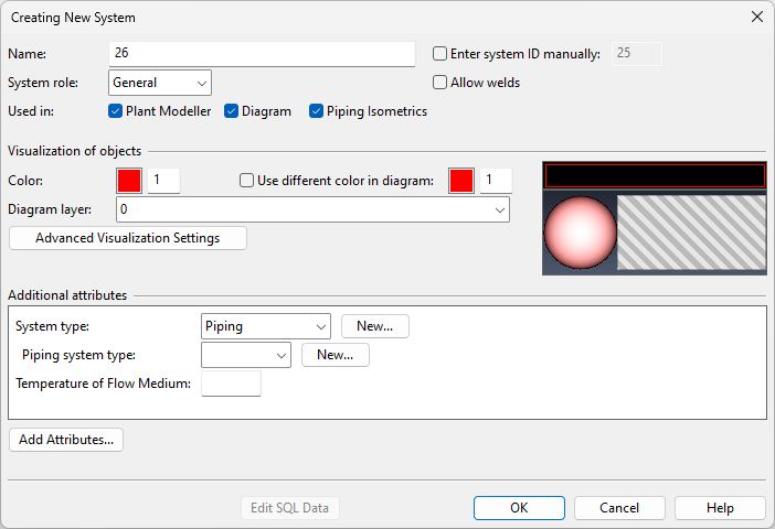
Select Systems > Define. The Creating New System dialog opens.
-
Enter the following information for the new system.
Setting
Description
The system's name can contain up to 100 characters, and any characters beyond this limit are truncated.
You cannot use unprintable ASCII control codes (ASCII table character codes 0-31) in the name.
Spaces inserted before the name are automatically removed.
The system ID number is a unique system identifier that cannot be changed later. Model objects store the system ID to bind themselves to a system.
You can either use the automatically assigned number or enter the system ID manually.
-
ID numbers 1–5999 can be used for user-defined systems.
-
ID numbers 6000–8191 are reserved by Cadmatic.
Specific sub-ranges are used in software integration. The systems that use these ID numbers are automatically created if the related software is installed:
-
ID numbers 6100–6199 are for NAPA related systems.
-
ID numbers 6200–6299 are for Tekla related systems.
Similarly, we recommend that user organizations reserve certain ranges for different purposes. For example, ID numbers 1-9 could be related to building, 10-19 to equipment, 300-400 to piping, and so on. This method makes it easier to make selections based on these ID ranges. For more information on setting the conditions for object selection, see Query test editor.
The system's role in the applications.
-
General – Most systems should have this role.
-
Cableway – Only systems that define cable trays should have this role. Selecting this role displays additional Definitions for Cable Router options.
-
Cable – Only systems that define cables should have this role. Selecting this role displays additional Definitions for Cable Router options.
For more information on the Cable Router related roles, see Cable tray systems and lines.
If selected, objects that use this system can be welded.
This setting is available when System role is either 'General' or 'Cableway'.
If selected, the system is visible in Plant Modeller.
If selected, the system is visible in P&ID, and you can define the options Use different color in diagram and Diagram layer.
If selected, the system is visible in Piping Isometrics & Spools.
Visualization of objects
The color of the system in non-shaded views.
The color can be selected from the Colors configuration by clicking the color palette or entering the index number of the desired color.
The color of the system in shaded views can be set in the Advanced Visualization Settings.
If selected, specifies the color of the system within the P&ID application.
The color can be selected from the Colors configuration by clicking the color palette or entering the index number of the desired color.
The layer where objects using this system are assigned when a P&ID diagram is exported. See also Drawing export configuration.
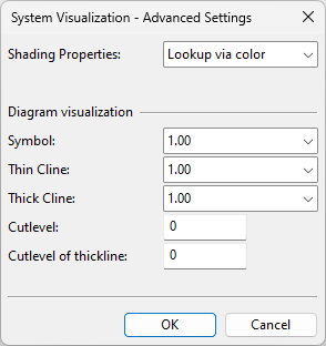
Opens the System Visualization – Advanced Settings dialog.
-
Shading Properties – If set to 'Lookup via color', the Color setting is used to find a matching color for shaded objects. Alternatively, you can select a particular shading style (which are defined in the Surface shading setup configuration) from the drop-down list.
-
Symbol – The linewidth of diagram symbols using this system.
-
Thin Cline – The linewidth of thin connection lines using this system.
-
Thick Cline – The linewidth of thick connection lines using this system.
-
Cutlevel – The cut level [0,255] of connection lines drawn with a thin line.
-
Cutlevel of thickline – The cut level [0,255] of connection lines drawn with a thick line, such as the 'Primary pipe' in the CADMATIC example project.
This works so that when thin and thick connection lines intersect and visual cuts are enabled in Cut Parameters, the line whose system has the smaller cut level value will be cut.
If System role is 'Cableway', select which interference classes to allow in cable trays that use this system.
If System role is 'Cable', select which interference class to assign to cables that use this system.
You can add and remove system attributes. Lines inherit their system's attributes, but they can also override the inherited value at line level.
For example, when a designer is selecting a system, an attribute based on a dynamic hierarchy can provide useful information to the designer.
-
-
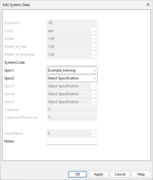
Click OK. The Edit System Data dialog opens.
-
Fill in the required values, and click OK.
Assign
You can use this command to assign a system to a set of diagram objects whose object type is Equipment.
Note: This command does not change the system of diagram objects that are assigned to a pipeline, instrument tag, or electric circuit. To change their system, you must use a specific command that assigns system and pipeline (Assign), system and instrument tag (Assign), or system and electric circuit (Assign) at the same time.
Do the following:
-
Select Systems > Assign. The Select system dialog opens.
-
You can filter the drop-down list to show only systems that no diagram is using by selecting Only unused systems.
-
Select the system to use, and click Assign.
-
Pick the required diagram objects, and press Enter to accept the set. The Select system dialog reopens.
-
You can continue assigning systems or click Close to stop.

Tip: For a single object you can also do this from the Property pane: in the Object's system name row, select … and then Change system.
Pipelines

The Pipelines button contains tools for creating pipelines and assigning pipelines to diagram objects.
Define | Assign | Define & assign
Define
You can use this command to create new pipelines.
Do the following:
-
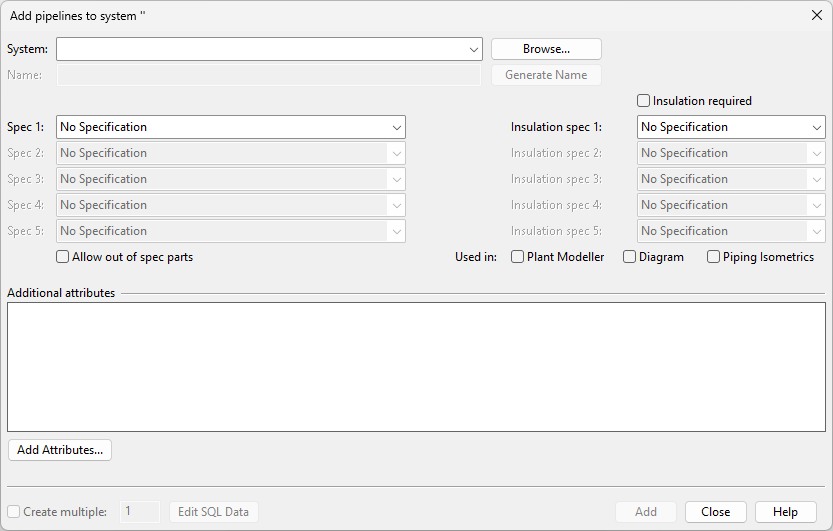
Select Pipelines > Define. The Add pipelines to system dialog opens.
-
Enter the following information for the new line.
Setting
Description
The system of the line.
The name of the line.
The default name is derived from the Name Generation Rules. You can edit the name here, and if necessary, you can restore the automatically generated name by clicking Generate Name.
Note: If you edit the name and then create multiple lines, only the first line will use the edited name—subsequent lines will still adhere to the name generation rules.
The specifications that the pipeline, ductline, or cable tray is to use.
If selected, also parts not included in specifications can be used in the line.
If selected, designers must select at least one insulation specification when routing a pipeline or ductline.
The insulation specifications that the pipeline or ductline is to use.
If selected, the pipeline is visible in Plant Modeller.
If selected, the pipeline is visible in P&ID.
If selected, the pipeline is visible in Piping Isometrics & Spools.
Either allows the cable tray to inherit the interference classes from the system or specifies the interference classes the cable tray is to use.
You can add and remove line attributes. Model objects inherit their line's attributes, but they can also override the inherited value at object level.
-
Select Create multiple to create more than one pipeline, and specify the number of pipelines to create.
-
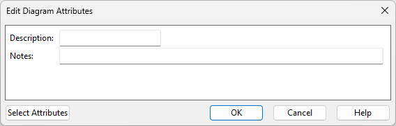
Click Add. The Edit Diagram Attributes dialog opens.
-
Define the SQL data for the pipelines to be created, and click OK.
-
You can continue creating new pipelines or click Close to stop.

Assign
You can use this command to assign a pipeline to a set of diagram objects whose properties include Pipeline.
Do the following:
-
Select Pipelines > Assign. The Select Pipeline dialog opens.
-
You can filter the drop-down list to show only pipelines that no diagram is using by selecting Only unused Pipelines.
-
Select the pipeline to use, and click Assign.
-
Select the diagram objects to which to assign the pipeline, and press Enter. The Select Pipeline dialog opens again.
-
You can continue assigning pipelines or click Close to stop.

Tip: For a single object you can do this from the Property pane: in the Name of object's pipeline row, select … and then Change pipeline.
Define & assign
You can use this command to create a new pipeline and assign the pipeline to a set of diagram objects whose properties include Pipeline.
Do the following:
-
Select Pipelines > Define & assign. The Add pipelines to system dialog opens.
-
Select the system to use. The default pipeline name is generated with Name Generation Rules.
-
Edit the pipeline name if necessary, and click Add. The Edit Diagram Attributes dialog opens.
-
Define the SQL data for the pipeline to be created, and click OK.
-
Pick the required diagram objects, and press Enter to accept the set. The Add pipelines to system dialog opens again.
-
You can continue creating and assigning pipelines, or click Close to stop.
Instrument Tags

The Instrument Tags button contains tools for creating instrument tags and assigning instrument tags to diagram objects.
Instrument tags are administrative objects for instrumentation/control loops, like pipelines are administrative objects for pipe runs. Typically, a single system can be used for all instrument type objects. You can use instrument tags for identifying all the instruments in the project, for example for listing purposes. Typical instrument tag objects are measurement or signal lines and controllers between them.
Define | Assign | Define & assign | Edit | Delete
Define
You can use this command to create a new instrument tag.
Do the following:
-
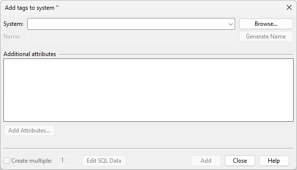
Select Instrument Tags > Define. The Add tags to system dialog opens.
-
Select the system to use. The default tag name is generated with Name Generation Rules.
-
Edit the name if necessary, select whether to create more than one tag (subsequent tags will use generated names), and click Add. The Edit Diagram Attributes dialog opens.
-
Enter the required attribute values, and click OK. The new instrument tag is saved in the database.
Assign
You can use this command to assign an instrument tag to a set of diagram objects whose properties include Instrument Tag.
Do the following:
-
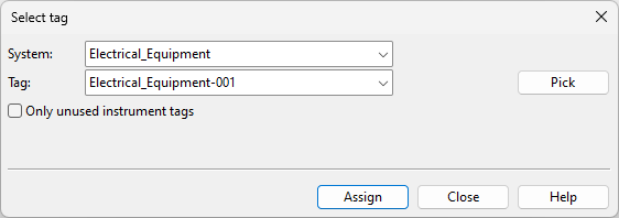
Select Instrument Tags > Assign. The Select tag dialog opens.
-
You can filter the drop-down list to show only instrument tags that no diagram is using by selecting Only unused instrument tags.
-
Select the instrument tag to use, and click Assign.
-
Select the diagram objects to which to assign the instrument tag, and press Enter. The Select tag dialog opens again.
-
You can continue assigning instrument tags or click Close to stop.
-
Save the diagram.
Assign System and Instrument Tag
Define & assign
You can use this command to create a new instrument tag and assign the instrument tag to a set of diagram objects whose properties include Instrument Tag.
Do the following:
-
Select Instrument Tags > Define & Assign. The Add tags to system dialog opens.
-
Select the system to use. The default tag name is generated with Name Generation Rules.
-
Edit the name if necessary, and click Add. The Edit Diagram Attributes dialog opens.
-
Enter the required attribute values, and click OK.
-
Select the diagram objects to which to assign the tag, and press Enter. The Add tags to system dialog opens again.
-
You can continue creating and assigning tags, or click Close to stop.
Edit
You can change the name or edit the attributes of an instrument tag.
Do the following:
-
Select Instrument Tags > Edit. The Select tag dialog opens.
-
Select the instrument tag you want to edit.
-
Do one of the following:
-
To rename the instrument tag, click Rename.
-
To edit the attribute values of the instrument tag, click OK.
-
To exit the tool without making any changes, click Close.
-
Delete
You can use this command delete instrument tags that are not used in any diagram from the database.
Do the following:
-
Select Instrument Tags > Delete. The Select dialog opens, listing the systems that have instrument tags.
-
Select the required system. The Select dialog opens, listing the instrument tags of the selected system.
-
Select the instrument tags to be deleted, and click OK. The message pane indicates if any of the selected instrument tags are still in use and could not be deleted.
-
Save the diagram.
Electric Circuits

The Electric Circuits button contains tools for creating electric circuits and assigning diagram objects to electric circuits.
Note: Electric circuits cannot be exported into the 3D model.
Define | Assign | Define & assign | Edit | Delete
Define
You can use this command to create a new electric circuit.
Do the following:
-
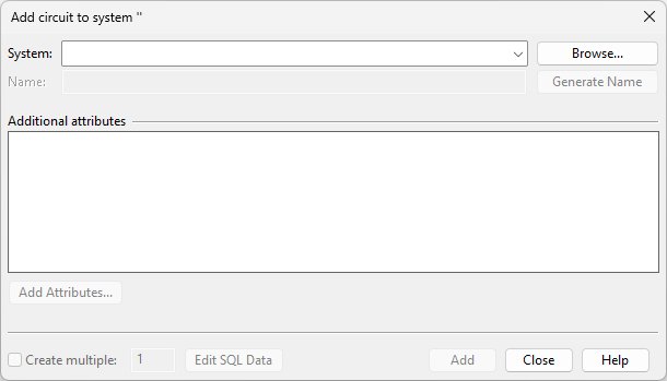
Select Electric Circuits > Define. The Add circuit to system dialog opens.
-
Select the system to use. The default circuit name is generated with Name Generation Rules.
-
Edit the name if necessary, select whether to create more than one circuit (subsequent circuits will use generated names), and click Add. The Edit Diagram Attributes dialog opens.
-
Enter the required attribute values, and click OK. The new electric circuit is saved in the database.

Assign
You can use this command to assign an electric circuit to a set of diagram objects whose properties include Electric Circuit.
Do the following:
-
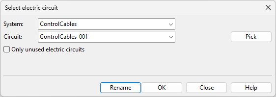
Select Electric Circuits > Assign. The Select electric circuit dialog opens.
-
You can filter the drop-down list to show only electric circuits that no diagram is using by selecting Only unused electric circuits.
-
Select the electric circuit to use, and click Assign.
-
Select the diagram objects to which to assign the electric circuit, and press Enter. The Select electric circuit dialog opens again.
-
You can continue assigning electric circuits or click Close to stop.

Assign System and Electric Circuit
Define & assign
You can use this command to create a new electric circuit and assign the electric circuit to a set of diagram objects whose properties include Electric Circuit.
Do the following:
-
Select Electric Circuits > Define & Assign. The Add circuit to system dialog opens.
-
Select the system to use. The default circuit name is generated with Name Generation Rules.
-
Edit the name if necessary, and click Add. The Edit Diagram Attributes dialog opens.
-
Enter the required attribute values, and click OK.
-
Select the diagram objects to which to assign the electric circuit, and press Enter. The Add circuit to system dialog opens again.
-
You can continue creating and assigning electric circuits, or click Close to stop.
Edit
You can change the name or edit the attributes of an electric circuit.
Do the following:
-
Select Electric Circuits > Edit. The Select electric circuit dialog opens.
-
Select the electric circuit you want to edit.
-
Do one of the following:
-
To rename the electric circuit, click Rename.
-
To edit the attribute values of the electric circuit, click OK.
-
To exit the tool without making any changes, click Close.
-
Delete
You can use this command delete electric circuits that are not used in any diagram from the database.
Do the following:
-
Select Electric Circuits > Delete. The Select dialog opens, listing the systems that have electric circuits.
-
Select the required system. The Select dialog opens, listing the electric circuits of the selected system.
-
Select the electric circuits to be deleted, and click OK. The message pane indicates if any of the selected electric circuits are still in use and could not be deleted.
-
Save the diagram.
Position IDs

The Position IDs tool allows reserving position IDs and pipeline names. Pipeline names are reserved inside P&ID only—it is possible to create a pipeline with the same (reserved) name in Plant Modeller. If integration is in use, the reservation can be seen also in Plant Modeller; if a user tries to insert a position ID that has been reserved in P&ID, the application notifies the user, but the user can still decide to ignore the reservation.
The Position IDs button opens the Manage Reserved PosIds dialog.

The Manage Reserved PosIds dialog has these columns:
|
Column |
Description |
|---|---|
|
Table name |
Name of database table that uses the position IDs. |
|
Class |
Specifies the prefix of the position ID or line number before consecutive numbering. |
|
Min |
Lowest value in the reserved range of consecutive numbers. |
|
Max |
Highest value in the reserved range of consecutive numbers. |
|
Info |
Optional text field for providing additional information. |
|
Diagram |
Optional text field that specifies which diagram will use the reserved numbers. |
Use these buttons to manage the reservations:
-
New – Allows creating a new reservation. Does not check if the position ID has been reserved or used in the diagram before.
-
Add – Allows creating a new reservation. Checks which position IDs are already in use and reserves only the ones that are free.
-
Free – Allows removing single position IDs.
-
Modify – Allows modifying the currently selected reservation row.
-
Delete – Deletes the selected reservation row.


EDM
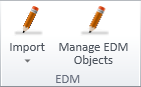
On the Insert tab, the EDM group contains tools for importing object data from external sources to COS and then linking this data to diagram objects as additional attributes.
Import
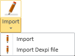
The Import button contains tools for importing external data from a CADMATIC XML or DEXPI XML file to the COS database.
After the import, you can link the imported EDM objects to diagram objects, as described in Manage EDM Objects.
Importing a CADMATIC XML File
You can import EDM objects from CADMATIC XML format.
Prerequisites
- The required data mappings have been defined as described in Edit settings.
Do the following:
-
On the Insert tab, select Import > Import.
-
In the file browser, select the XML file from the file system, and click Open.
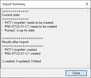
-
The Import Summary dialog lists the import results. Review the summary and click Close to close it.
The imported EDM objects are now stored in the COS database.
Importing a DEXPI XML File
You can import EDM objects whose type is Equipment from DEXPI XML format. These objects can link externally provided data directly to CADMATIC 3D or P&ID objects.
You cannot import objects whose type is Valve or Instrument. You cannot import pipelines or systems, or sub-items such as nozzles.
If the file contains objects whose External ID is already in COS, the import updates the data in COS.
Prerequisites
- The required data mappings have been defined as described in Edit settings.
Do the following:
-
On the Insert tab, select Import > Import DEXPI File.
-
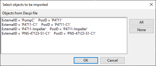
In the file browser, select the DEXPI XML file from the file system, and click Open.
-
The Select objects to be imported dialog lists the objects of the XML file, displaying their External ID, Tag, and Position ID.
-
The Import Summary dialog lists the import results. Review the summary and click Close to close it.
The imported EDM objects are now stored in the COS database.
Manage EDM Objects

You can link an EDM object to a diagram object to assign externally defined attributes to the diagram object. If the EDM object is updated in COS, also the diagram object gets the updates.
If the EDM object has been linked to a 3D model object, updating integration data from P&ID to the 3D model creates an integration link (an EPD object) between the diagram object and the 3D object.
Do the following:
-
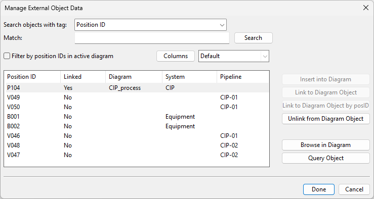
On the Insert tab, select Manage EDM Objects. The Manage External Object Data dialog opens. You can click Columns to select which columns to show in the dialog.
-
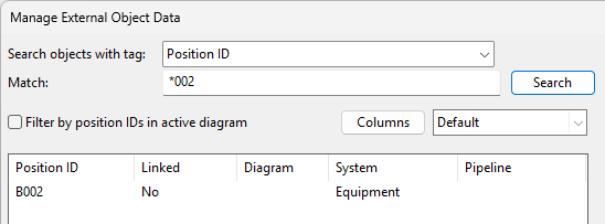
To find a specific EDM object, you can do one of the following.
-
Select which tag to search, enter the search text (asterisk "*" functions as a wildcard), and click Search.
-
Select Filter by position IDs in active diagram to hide all those EDMs whose position ID is not in the active diagram.
-
-
To manage the linking, select an EDM object and then the appropriate action.
Note: This tool does not show EDM objects that have the "External Position ID Status" attribute set to "Deleted".
-
Insert into Diagram – Select this to insert a new diagram object that will then be linked to the EDM object. If you select this but the position ID of the EDM object is already in the active diagram, you are prompted whether to link to that object instead of inserting a new one.
-
Link to Diagram Object – Select this to pick the diagram object from the active diagram. If the EDM object has a different position ID, the position ID of the diagram object is used.
-
Link to Diagram Object by posID – Select this to link the EDM object to the diagram object that has the same position ID, if found in the active diagram.
-
Unlink from Diagram Object – Select this to remove the link between the EDM object and the diagram object.
-
Browse in Diagram – Zooms to the linked diagram object in the active diagram.
-
Query Object – Shows the database data of the linked diagram object in a separate dialog.
-
-
Click Done.