Splitting isometric groups
When using the Create New Isometric Group dialog, the automatic splitting function can divide large isometric groups into smaller isometric groups. In some cases, you might want to adjust the results of this automatic splitting manually.
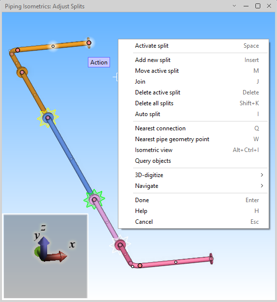
Selecting a pipeline and then clicking the Manual Splitting button opens the Adjust Splits view. There, you can see the objects in the pipeline and adjust the distribution of parts into isometric groups. This is done by adding, moving, and deleting split points, which must be located at a connection point or pipe geometry point.
Split points between isometric groups are marked with transparent, star-shaped objects: automatically inserted markers are yellow, manually inserted markers are green, and the active (selected) marker is light gray.
Right-click the view to access the following commands.
Note: There is no undo functionality within this tool, but you can cancel all changes when exiting the editing session.
Activate split (Space)
Certain commands require one of the splits to be active. To activate a split, move the cursor to the split marker and press Space or click it. The split marker color changes to light gray.
Add new split (Insert)
You can add a split point to assign the piping objects on both sides of the given point to different isometric groups. To do this, navigate to the required location using either Nearest connection (Q) or Nearest pipe geometry point (W) and then select this command.
This action prompts you to confirm the insertion when it is located between two different face types, next to a bent pipe, if the pipe needs to be cut, or if the split is inside a spool.
When a new split is inserted, a split marker appears in that location and a new isometric group is created. This also changes the color of the objects on the other side of the split point. If a spool was broken, a new spool that contains the parts on the other side of the split point is created.
Move active split (M)
You can move a split to a different location. To do this, activate the split, navigate to the new location using either Nearest connection (Q) or Nearest pipe geometry point (W), and then select this command. The parts on both sides of the original and new split location are reassigned to isometric groups as required.
Join (J)
You can move pipes from different isometric groups to a single isometric group. To do this, select this command, select the objects, and then press Enter.
This action also removes any split points defined in the original isometric groups.
Delete active split (Delete)
You can remove an automatically or manually added split by activating the split and then selecting this command. The objects on both sides of the removed split are assigned to a single isometric group.
This action does not join pipes or modify spools in any way.
Delete all splits (Shift+K)
You can remove all automatically and manually added splits to assign all objects to a single isometric group. You are prompted to confirm the action.
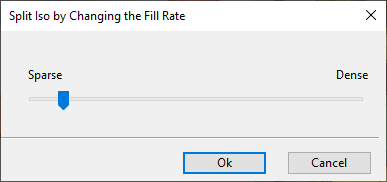
Auto split (I)
You can perform automatic splitting for all objects. Selecting this command opens the Automatic Split dialog for defining how many isometric groups to create. This allows you to override the default object density defined in Automatic splitting rules for isometric groups.
-
Click Increase to create more groups. There will be more drawings but fewer objects per drawing.
-
Click Decrease to create fewer groups. There will be fewer drawings but more objects per drawing.
Clicking OK performs automatic splitting and shows the results in the Adjust Splits view.
Nearest connection (Q)
Select this command to navigate and lock the cursor to the nearest pipe connection point.
You can do this before using Add new split (Insert) or Move active split (M).
Press Space or click the view to release the cursor if needed.
Nearest pipe geometry point (W)
Select this command to navigate and lock the cursor to the nearest pipe geometry point.
You can do this before using Add new split (Insert) or Move active split (M).
Press Space or click the view to release the cursor if needed.
Isometric view (Alt+Ctrl+I)
You can rotate the Adjust Splits view by holding down the middle mouse button and dragging the mouse; click to keep the current angle.
When the view is rotated, you can use this command to restore the original isometric view direction.
Query objects
Normally, the Adjust Splits view only allows you to select split point markers.
When you select this command, you can select any object from the view and press Enter to open the Object properties dialog to display the properties of that object.
Done (Enter)
Select this command to keep your changes and return to the Create New Isometric Group dialog.
Help (H)
Select this command to open this help topic.
Cancel (Esc)
Select this command to cancel your changes and return to the Create New Isometric Group dialog. You are prompted to confirm the action.
Canceling the changes also removes any pipe cuts made during the session.