Beam Tool

The Beam Tool dialog provides the most-often used commands for adding and modifying beams. You can use it, for example, to change the beam profile, rotate, trim, and stretch beams, and add and remove end cuts.
Accessing the beam tool
The beam tool is part of the default CADMATIC Plant/Outfitting installation, but it is delivered as a script file. You can either run the script file from the file system or add a button for the beam tool to the Plant Modeller ribbon.
To open the beam tool by running the script file, do the following:
-
On the Tools tab, click Script, select the file %PMS_RUNDIR%\pm\macro\BeamTool.bs, and click Open.
To add the beam tool to the Plant Modeller ribbon, do the following:
-
In the CADMATIC desktop, select Object > Library and Project Databases.
-
In the Project Environment dialog, browse to [library or project] > Resources > Custom UI.
-
Select New > Custom UI, enter a descriptive name (such as "Beam Tool"), and click OK to save the Custom UI object.
-
Open the new Custom UI object in a text editor, write the customization code in it, and save and close the file.
 Show/hide example
Copy
Show/hide example
Copy<RibbonSettings>
<Ribbon Name="main">
<RibbonTab Name="structuralTab">
<TabGroup Name="structuralTabBeamPanel">
<CustomCommand Name="Beam Tool" Index="0" CommandData="C:\CADMATIC\co223\pms2230.nt\pm\macro\BeamTool.bs main()" Hotkey="Alt+B" />
</TabGroup>
</RibbonTab>
</Ribbon>
</RibbonSettings> -
Check in the Custom UI object.
-
If you created the Custom UI object in the library, approve it for use in the project.
-
Start Plant Modeller. You should now be able to access the beam tool from the ribbon.
For more information on customizing the ribbon, see Customizing the ribbon.
Inserting beams with the beam tool
You can use the Beam Tool dialog to insert and modify beams.
Prerequisites
-
To use this tool, there must be at least one beam specification in the project. Beam specifications make it possible to have several named sets of beams for different purposes, for instance to make pipe support frameworks with specific types of beams. For more information on beam specifications, see Beam specifications.
Do the following:
-
Open the Beam Tool dialog as described in Accessing the beam tool.
-
Define General beam properties such as the System and the specification that the new beams are to use.
-
In the Beam section, select a Class and Profile or click Pick from model to copy them from an existing beam.
-
In the Cross Section box, click the point where you want the routing point to be and use the buttons Define, << and >> to define beam rotation, if needed.
-
Click Insert Beam. The Beam Tool dialog closes.
-
In the active work view, first select and accept the start point (where to place the routing point of the beam profile), and then select and accept the end point. The beam is inserted between the specified points.
-
You can continue to insert more beams of the same type, or press Esc to return to the Beam Tool dialog.
-
You can modify the inserted beams with the commands available in the Beam Tool dialog, or you can close the dialog and use the tools in the Beam and Edit groups of the Structural tab.
Beam Tool dialog
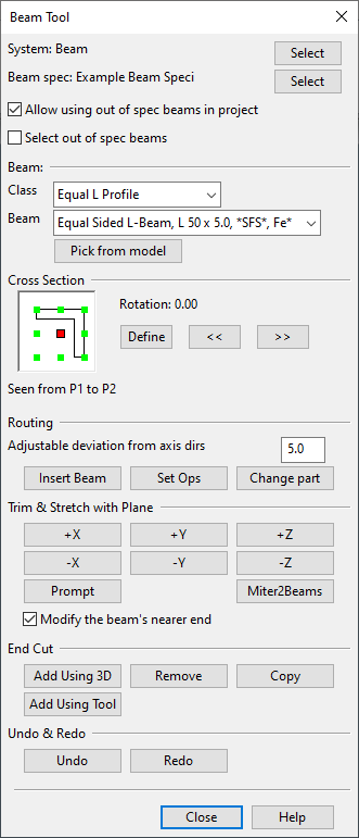
The Beam Tool dialog is divided into tool groups, as described below.
General beam properties
At the top of the Beam Tool dialog you can manage the general beam properties.
- System – Displays the currently selected system. Click Select to change the system using the object browser. For more information on object browsers, see Object browser.
- Beam spec – Displays the currently selected beam specification. Click Select to change the specification.
- Allow using out of spec beams in project – If selected, out-of-spec beams are allowed in the project.
- Select out of spec beams – If selected, the Class and Beam drop-down menus allow selecting out-of-spec beams.
Beam
In the Beam section you can specify what kind of beam to use. You can select the Class and Beam values from the drop-down menus, or you can populate them by picking an existing beam from the model.
- Class – Select the beam class (beam profile) from the drop-down menu.
- Beam – Select the profile size from the drop-down menu. The list shows all the beam sizes of the catalog parts assigned to the current beam class in the current beam specification. The list string of each item is made by adding the catalog part dimensional description to the part description.
- Pick from model – Pick an existing beam from the model and press Enter to retrieve the Class and Beam values from the specified beam.
Cross Section
The Cross Section box displays an interactive cross-section representation of the beam, as seen from the starting point of routing towards the end point.

Beams have a routing point that you use to place the beam in the correct location and to align it with other objects. In the cross section view, the small green squares are possible routing points, and the big red square is the currently selected routing point. You can change the routing point by clicking the green square where the routing point should be.
The Cross Section box also displays the rotation of the beam. You can rotate the beam 45 degrees clockwise or counter-clockwise by clicking the arrow buttons. Or, you can click Define to enter a specific rotation value as degrees counter-clockwise, relative to the beam cross section.
Routing
In the Routing section you can insert new beams, perform set operations, and change the part of an existing beam.
- Adjustable deviation from axis dirs – Defines the tolerance angle of aligning the routing vector to the nearest main axis direction. For example, if you route the beam so that the direction from the start point to the end point differs from the x axis direction less than this value, the system moves the end point so that the direction is parallel to the x axis.
- Insert Beam – Allows you to select the start point and the end point, and then inserts a beam using the currently defined cross section routing point and rotation angle.
- Set Ops – Opens the Set Operations tool where you can perform various operations on existing beams. You can, for example, move a beam to a more appropriate location or make multiple copies of a beam. See Set Operation Tool for details.
- Change part – Allows you to pick existing beam parts and then applies the current beam tool settings to those beams.
Trim & Stretch with Plane
You can adjust the length of a beam by trimming or stretching it. See Trim and Stretch.
End Cut
You can add, remove, and copy beam end cuts.
- Add Using 3D – Cuts beam end with a plane whose normal you define in the 3D view.
- Add Using Tool – Cuts beam end with a visual cutting tool. See End Cut Tool.
- Remove – Removes an end cut from a beam.
- Copy – Copies an end cut from one beam end to another.
For more details on adding, removing, and copying end cuts, see End Cut.
Undo & Redo
You can undo or redo the latest beam tool actions.