Examples of Script Functions
The following examples demonstrate the use of script extern functions.
Object Browser
The following example demonstrates how to:
-
pick an object
-
create a view
-
visualize the object into the view
Copy
/* Create an axonometric view around the selected object. */

#include include/dmutil.h
#include include/pm.h
main()
{
 cnt = TRUE;
 while(cnt == TRUE){
 /* Pick any object */
 nth = 0; /* returns the pipe segment number if
 PIPE object selected */
 obj = PM_PICK_OBJECT("Pick object",nth);
 /* If CANCEL pressed then make an
 early return */
 if(ISINT(obj))return(0);
 view_h = visualize_obj_in_axo_view(obj,"ObjView");
Copy
st = DM_CALL_SCRIPT("macro/ChooseAction.mac",
 "ChooseAction",
 "Object Browser",
 "Select Action",
 "Close View and Exit\nExit\nContinue"
 );
 if(st==1){
 PM_CLOSE_VIEW(view_h);
 return(0);
 }
 else if(st == 2){
 return(0);
 }
 }
}
visualize_obj_in_axo_view(obj,view_name)
{
 /*
 Check that a view with this name is
 not currently open
 */
 in_drawing = FALSE; /* false, since we are
 dealing with work views */
 v = PM_GET_HANDLE_OF_OPENED_VIEW(view_name,
 in_drawing);
 /*
 If 'v' is an integer then the view is not
 open. If 'v' is a valid handle the old view
 must be closed before creating a new one.
 */
 if( !ISINT(v) ){
 PM_CLOSE_VIEW(v);
 }
Copy
   /*
 Get the minimum bounding box of the object
 x,y,z coordinates
 */
 xmin = 0; xmax = 0; ymin = 0; ymax = 0;
 zmin = 0; zmax = 0;
 PM_GET_BBOX_OF_OBJECT(obj, xmin, xmax, ymin,
 ymax, zmin, zmax);
 /* Create an axonometric view */
 v = create_view(obj, view_name, xmin, ymin,
 zmax, -1, -1, 1);
 return(v);
}
/*
 Create a new view. Visualize the object.
 Zoom the view.
 Remove hidden lines
 and shade the view.
*/
Copy
create_view(obj,view_name,x,y,z, dx,dy,dz)
{
 /* We are making a work view -not a view
 of a drawing */
 into_drawing = FALSE;
 /* next two dummy arguments in this case: */
 screen = "";
 xserver = "";
 view = PM_CREATE_VIEW(view_name, into_drawing,
 screen, xserver);
 /*
 Set the view point, view direction,
 pipe centerline visibility.
 Also set the view to enclose the
 whole model
 */
 PM_SET_VIEW_PARAMETERS(view,"POINT",x,y,z,
 "VDIR", dx,dy,dz,
 "CL_NS_LIM",1,
 "LIMITS",0,0,0,0,0);
Copy
    /*
 We need to have a PM set to be able to
 visualize the object
 in the view
 */
 set = PM_INIT_SET();
 PM_ADD_OBJECT_TO_SET(obj, set);
 PM_VISUALIZE_SET_TO_VIEW(set, view);
 /* The temporary set is not needed any more */
 PM_FREE_SET(set);
 /*
 Get the limits of the bounding box that
 encloses all objects
 visualized so far
 */
 umin = 0; umax = 0; vmin = 0; vmax = 0;
 wmin = 0; wmax = 0;
 PM_GET_VIEW_PARAMETERS(view, "BBOX", umin,
 umax, vmin, vmax, wmin, wmax);
 /* Margin at the sides of the view after
 zooming */
 margin = 100;
 /* Zoom the view */
 PM_SET_VIEW_PARAMETERS(view, "WINDOW",
 umin - margin, umax + margin, vmin -
 margin, vmax + margin );
 /* Remove hidden lines and shade */
 PM_RM_HLINES_FROM_VIEW(view);

 /*
 Could be shaded too
 PM_SHADE_VIEW(view,0);
 */
 return(view);
}

/*
 Boolean function
 Return values: View exists == 1 (true),
 view does not exist == 0 (false)
*/
view_exist(vn)
{
 next = 0;
 go_on = 1;
 status = 0;
 while( go_on){
 name = PM_GET_NAME_OF_NEXT_VIEW("", next,
 status);
 if(ISINT(name))return(0);
 if(name == vn)return(1);
 }
}
Browse Set via Walkaround
The following example demonstrates how to:
- define a set
- use the walkaround module to visualize the set
Copy
#include "include/dmutil.h"
#include "include/pm.h"
global float MaxDiagonal, SetMx, SetMy, SetMz;
global float Xmin, Xmax, Ymin, Ymax, Zmin, Zmax;

compute_box_for_set(set)
{
 nr = PM_NR_MEMBERS_IN_SET(set);
 Xmin = 0; Xmax = 0;
 Ymin = 0; Ymax = 0;
 Zmin = 0; Zmax = 0;
 PM_GET_BBOX_OF_SET(set,Xmin,Xmax,Ymin,Ymax,Zmin,
 Zmax);
 SetMx = (Xmin + Xmax)/2;
 SetMy = (Ymin + Ymax)/2;
 SetMz = (Zmin + Zmax)/2;
 MaxDiagonal = SQRT((Xmax-Xmin)*(Xmax-Xmin) +
 (Ymax-Ymin)*(Ymax-Ymin) +
 (Zmax-Zmin)*(Zmax-Zmin));
}

/* replace this with your own pick object handler as needed */
pickhandler(obj, nth_pc)
{
 U_MESSAGE("Some object has been picked.");
 return(0);
}
/*
 Interface of this tool script.
 You can call WalkAroundSet from other scripts
 with PM_CALL_SCRIPT
 external function.
*/
WalkAroundSet(set,shadingrules)
{
 compute_box_for_set(set);
 /*
 ** Camera position is given so that
 ** PM can compute
 ** viewing angle or
 ** move the camera so that the box that
 ** we specify
 ** becomes completely visible.
 ** We'll request that the first image
 ** is generated so that all of the
 ** set is visible.
 */
 viewangle = 45;
 dz = (Zmax - Zmin)/2;
 dy = (Ymax - Ymin)/2;
 if (dz > dy)
 d = dz;
 else
 d = dy;
 camera_x = SetMx + 2000;
 camera_y = SetMy + 2000;
 camera_z = SetMz + 2000;
 mrg = 50;
Copy
     r = PM_WALKAROUND(set, "CAMERA", camera_x,
 camera_y, camera_z,
 "TARGET", SetMx, SetMy,
 SetMz,
 "VIEWANGLE", viewangle,
 "SHOWBOXMINP", Xmin-mrg,
 Ymin-mrg, Zmin-mrg,
 "SHOWBOXMAXP", Xmax+mrg,
 Ymax+mrg, Zmax+mrg,
 "BACKPLANEDIST",
 MaxDiagonal/2,
 "PERSPECTIVE", 1,
 "ROTATE_CAMERA", 1,
 "SHADINGRULES",
 shadingrules,
 "PICKHANDLER",
 "pickhandler",
 "WALKDIR", 1, 0, 0);
 if (r == 0)
 U_MESSAGE("Settings saved");
 else if (r == 1)
 U_MESSAGE("Settings not saved");
 else
 U_MESSAGE("Interface error");
}
/*
 A main function for testing
*/
main()
{
 set = PM_DEFINE_SET("Set for walkaround.");
 if (set == 0) return(-1);
 WalkAroundSet(set,"NormalShading.ssr");
}
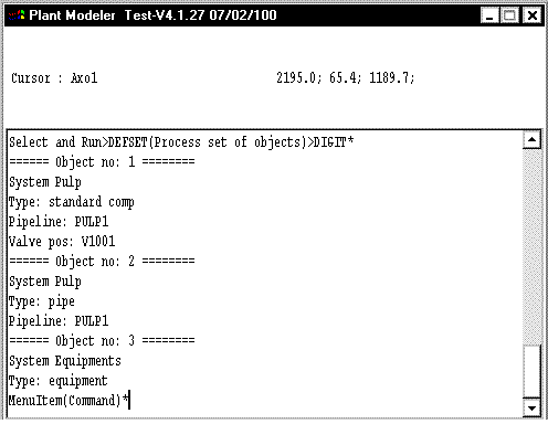
Accessing Object Data
The following example demonstrates how to:
- define a set
- scan a set
- access data of an object
Copy
/*
 Accessing data of a selected set of objects
*/

#include include/dmutil.h
#include include/pm.h

main()
{
 /* define the set interactively */
 set = PM_DEFINE_SET("Process set of objects");
 /* CANCEL pressed ? */
 if(ISINT(set))return(0);
 n_items = PM_NR_MEMBERS_IN_SET(set);
 /* scan all objects in the set */
 for(i=0; i<n_items; i=i+1;){
 obj = PM_GET_MEMBER_IN_SET(set, i);

 /*
 Extract data via a tag.
 see "VOL 2: Plant Modeller
 Administration: Customizing Documents"
 for list of available object tags
 NOTICE that all tag values are
 character strings even if they
 describe a number !
 */
 U_MESSAGE("====== Object no: "
 +ITOASCII(i+1)+ " ========");
 sys = PM_GET_OBJDATA(obj,0,"sys");
 U_MESSAGE("System "+sys);
 /* Object type */
 obt = PM_GET_OBJDATA(obj,0,"obt");
 /* Actually there are no "extra materials"
 in the 3D model */
 if( obt == "0" )type = "extra material";
 else if( obt == "1" ){
 U_MESSAGE("Type: equipment");
 }
 else if( obt == "2" ){
 U_MESSAGE("Type: standard comp");
 pli = PM_GET_OBJDATA(obj,0,"pli");
 U_MESSAGE("Pipeline: "+pli);
 vpo = PM_GET_OBJDATA(obj,0,"vpo");
 if(! ISINT(vpo)){
 U_MESSAGE("Valve pos: "+vpo);
 }
 ipo = PM_GET_OBJDATA(obj,0,"ipo");
 if(! ISINT(ipo)){
 U_MESSAGE("Instr. pos: "+ipo);
 }
 }
 else if( obt == "4" ){
 U_MESSAGE("Type: structural");
 }
 else if( obt == "5" ){
 U_MESSAGE("Type: beam");
 }
 else if( obt == "6" ){
 U_MESSAGE("Type: HVAC");
 }
 else if( obt == "9" ){
 U_MESSAGE("Type: piping part");
 pli = PM_GET_OBJDATA(obj,0,"pli");
 U_MESSAGE("Pipeline: "+pli);
 }
 else if( obt == "14" ){
 U_MESSAGE("Type: attribute");
 }
 else if( obt == "15" ){
 U_MESSAGE("Type: group");
 }
 else {
 U_CONFIRM("Unknown object type<" +
 obt+"> !!");
 return(-1);
 }
 }
 /* free the temporarily allocated memory */
 PM_FREE_SET(set);
}

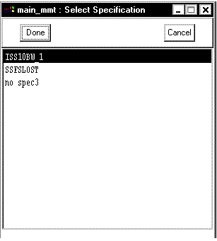
Query Specification of a PIPE/STDCOMP
The following example demonstrates how to:
- pick a PIPE or STDCOMP object
- extract piping specification which was used when the object was built
- make a selection tool with the "advanced" user interface tools
Copy
/*  We use a selection tool for showing the current spec yet the selection does not have any meaning in this context. */
#include "include/dmutil.h"
#include "include/pm.h"
main()
{
 cont=TRUE;
 /* Examine all objects in one loop */
 while(cont==TRUE){

 obsolete = 0;
 /* get the handle of the STDC or PIPE object. Ignore other object types */
 obj = PM_PICK_OBJECT( "Object to examine spec", obsolete, "STANDCMP","PIPE");
Copy
         /*
 It is very typical that externs and
 script functions which return
 a valid handle when succeed return
 integer 0 when they fail.
 Thus a common method to trace success
 is to compare the type
 of the variable which receives the
 return value against type:
 INTEGER.
 If the type of the variable IS integer
 the call failed, otherwise
 the call succeeded.
 the following expression returns either
 TRUE or FALSE:
 ( NOT ( variable IS INTEGER) )
 */
 if( ! ISINT(obj) ){
 /* hi-light while extracting data */
 PM_HIGHLIGHT_OBJECT(obj, 1);
 /* get the name of a selected spec */
 spec = get_spec( obj );
 if( ISINT(spec) ){
 U_MESSAGE("No spec selected");
 }
 else {
 U_MESSAGE(
 "Specification selected : " +
 spec);
 }
 /* hi-light off */
 PM_HIGHLIGHT_OBJECT(obj, 0);
 cont = U_YESNO("OK to Continue",1);
 }
 else cont = FALSE;
 }

 return(0);
}

/*
** Get the name of the selected specification
** Return int 0 if error
*/
get_spec( handle obj )
{
 /* object's pipeline */
 pli = PM_GET_OBJDATA(obj, 0, "pli");
 if( ISINT(pli) ){
 U_MESSAGE("Error");
 return(0);
 }
 /* pipeline is a group object, so get
 it's handle */
 pli_h = PM_FIND_BY_NAME(pli);
 if( ISINT(pli_h) ){
 U_MESSAGE("Error");
 return(0);
 }
 /* the three specs of the pipeline: */
 ps1 = PM_GET_OBJDATA(pli_h,0,"ps1");
 ps2 = PM_GET_OBJDATA(pli_h,0,"ps2");
 ps3 = PM_GET_OBJDATA(pli_h,0,"ps3");
 if( ISINT(ps1) & ISINT(ps2) & ISINT(ps3) ){
 U_MESSAGE("No specs in pipeline "+pli+
 " !! ??" );
 return(0);
 }
 sel = A_ALLOC(3);
 if( ISINT(ps1) )
 A_PUT(sel,0,"no spec1");
 else
 A_PUT(sel,0,ps1);
 if( ISINT(ps2) )
 A_PUT(sel,1,"no spec2");
 else
 A_PUT(sel,1,ps2);
 if( ISINT(ps3) )
 A_PUT(sel,2,"no spec3");
 else
 A_PUT(sel,2,ps3);
 default = 0;
 /* spec of the object */
 obj_spc = PM_GET_OBJDATA(obj,0,"spc");
 /* set the default selection to be the spec
 of the object */
 if( ! ISINT(obj_spc) ){
 for( i=0; i<3; i=i+1; ){
 if( A_GET(sel,i) == obj_spc ){
 default = i;
 i = 3;
 }
 }
 }
 else {
 U_MESSAGE("Out of Spec Component");
 }
 seltool = "macro/../../dm/macro/Select.mac";
 selected = PM_CALL_SCRIPT(seltool, "U_Select",
 "Select Specification", 3, sel, default);
 /* Canceled ?*/
 if( selected < 0 ){
 A_FREE( sel ); /* avoid memory leaks */
 return(0);
 }
 spec = A_GET(sel,selected);
 /* User selected a "dummy" entry */
 if( HEAD(spec,3) == "no " ){
 U_MESSAGE("Dummy spec selected");
 A_FREE( sel );
 return(0);
 }
 A_FREE( sel );
 return( spec );
}

Building Model by Writing/Reading MDLs
The following example demonstrates how to:
- get 3D points
- use 2D arrays to store data
- build new objects via MDL files
Copy
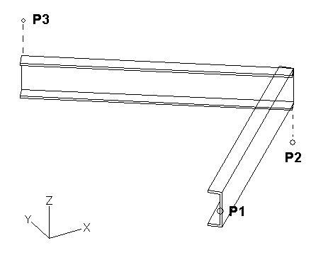
/*
 This script "routes" a set of beams on a
 horizontal plane.
 A set of points is first collected into a 2D
 array.
 The z-coordinate of the first point is the
 z-level of the
 routing.
*/
#include "include/dmutil.h"
#include "include/pm.h"
#include "include/geoutils.h"
#include "include/array.mac"
/* 'modebits' parameter of the PM_READ_MDL() function: */
#define READ_MDL_AS_MODULE 1
#define READ_MDL_COPY_EXISTING_OBJECTS 2
#define READ_MDL_MIRROR_Y 4
/* 'type' parameter of the PM_CREATE_TMAT()
 function: */
#define TMAT_TYPE_LOCAL_Z_DIR 0
#define TMAT_TYPE_LOCAL_X_Y_DIRS 1
#define TMAT_TYPE_LOCAL_Z_X_DIRS 2
#define TMAT_TYPE_LOCAL_X_DIRS 3
/* Part id of the beam to be routed */
/*
 NOTICE this PID is profile in the example
 project.
 It is not necessaryly present in YOUR project
*/
global string SteelPid = "SFS2026____-15";
/* The integer system id */
global int SysIdNumber = 5;
main()
{
 /* let the user to enter an array of points */
 points = 0;
 n_points = get_points( points );
 /* at least two points needed to define
 a beam */
 if( n_points <= 2 )return(-1);
 /* create beams according to the array
 of points */
 create_beams(n_points, points);
 /* free array of points */
 free_2darray(points);
 return(0);
}
/*
 Collect points
*/
get_points(points)
{
 a_pts = 0; /* number of allocated point
 rows */
 n_pts = 0; /* number of used point rows */
 pts = 0; /* handle to the points-array */

 /* create a new trace point structure
 - notice that these are freed
 when the script terminates */
 tracep = PM_NEW_TRACEP();
 x = 0; y = 0; z = 0;
 /* loop until DONE or CANCELed */
 cont = 1;
 while( cont ) {
 PM_GET_CURRENT_LOC(x,y,z);
 key = PM_GET_POINT("Point", tracep,
 x, y, z);
 /*
 key: the keyboard key which was
 pressed to accept the point.
 key < 0 == CANCELed
 key == 'space' (32) == POINT ACCEPTED
 key == 'F12' == ']' == (93) == DONE
 */
 if( key < 0 )
 return(-1);
 else if( key == 93 ){
 cont = 0;
 }
 else if( key == 32 ){
 /* alloc new space to array,
 if needed: */
 /* first time */
 if( a_pts == 0 ){
 a_pts = 5;
 pts = alloc_2darray(a_pts,3);
 }
 /* more space needed */
 else if(a_pts == n_pts){
 a_pts = a_pts + 5;
 realloc_2darray(pts,a_pts,3);
 }
 /* put {x,y,z} of the point into the
 2D array */
 put_2darray(pts,n_pts,0,x);
 put_2darray(pts,n_pts,1,y);
 put_2darray(pts,n_pts,2,z);
 n_pts = n_pts+1;
 }
 }
 /* update the handle of the 'points' array
 and return number of
 rows in the table */
 points = pts;
 return(n_pts);
}
Copy
create_beams(n_pts, pts)
{
handle tmat_h;
 /* Just need to have some legal filename */
 fn = "foo.mdl";
 /* The owner id number of the current area */
 owner = PM_GET_CURRENT_DESAREA();
 /* Create a new empty file */
 if( F_EXIST(fn) )F_DELETE_FILE(fn);
 F_CREATE_FILE(fn);
 f = F_OPEN_FILE(fn,"w");
 /* system number */
 sys = SysIdNumber;
 /* Get the z coordinate from the first point */
 z = get_2darray(pts,0,2);
 /* Scan all points. Create an MDL of beams
 from point to point */
 for(i=0;i<n_pts-1;i=i+1;){
 if( i > 0 )dump_end_of_record(f);
 x1 = get_2darray(pts,i,0);
 y1 = get_2darray(pts,i,1);
 x2 = get_2darray(pts,i+1,0);
 y2 = get_2darray(pts,i+1,1);
 dx = 0;
 dy = 0;
 dz = 0;
 dx1 = x1 - x2;
 dy1 = y1 - y2;
 dz1 = 0;
 /* convert deltas to unit vector
 components */
 VEC_UNITV(dx1,dy1,dz);
 dx2 = -dx1;
 dy2 = -dy1;
 dz2 = 0;
 /*
 Gets the local x-dir of the
 cross section , i.e. the
 rotation of the beam around its
 routing axis (routing direction).
 Here we use the vector cross product
 to get the correct direction.
 */
 st = VEC_CROSS_PRODUCT(dx1, dy1, dz1, 0, 0,
 1, dx, dy, dz);
 if( st ) {
 U_CONFIRM("Error in cross product");
 }
 /* Dump the MDL entry of one steel into a
 file */
 steel( f, SteelPid, owner, sys, x1, y1, z,
 x2, y2, z, dx, dy, dz, dx1, dy1, dz1,
 dx2,dy2,dz2 );
 }
 dump_end_of_mdl(f);
 f = F_CLOSE_FILE(f);

 /*
 No module, no copy, no mirror,
 tmat_h ignored since tmat_h is
 only used if loading MDL 'as module'
 */
 modebits = 0;

 /* The following tmat definition is a
 dummy one, but since the type of
 the 'tmat_h' argument is strictly checked by
 the system we must use a true transformation
 matrix handle here */
 tmat_h = PM_CREATE_TMAT(TMAT_TYPE_LOCAL_Z_DIR,
 x1, y1, z,0, 0, 1, 0, 0, 0);
 st = PM_READ_MDL(fn, modebits, "", tmat_h);
 if( st ){
 U_CONFIRM("Failed to read MDL in");
 return(-1);
 }
 return(0);
}
dump_end_of_record(f)
{
 /* a comma and a NEWLINE */
 F_PRINTF(f,",\n");
}
dump_end_of_mdl(f)
{
 /* just NEWLINE */
 F_PRINTF(f,"\n");
}
/*
 Create a BEAM record into the MDL file
 Arguments:
 f: file, pid: part_id, owner: design area id
 sys: system id, point1, point2,
 direction of local x of the cross section
 end cut direction at point1
 end cut direction at point2
*/
steel(f, string pid, int owner, int sys,
 x1,y1,z1,x2,y2,z2, dx,dy,dz,
 dx1,dy1,dz1, dx2,dy2,dz2)
{
 /* See documentation of MDL in VOL2. */
 F_PRINTF(f,"STEL(%s,ST(%d,ffffffff,%d,0,1),",
 pid,owner,sys);
 F_PRINTF(f,
 "P(%.2f,%.2f,%.2f),P(%.2f,%.2f,%.2f),",
 x1,y1,z1,x2,y2,z2);
Copy
    F_PRINTF(f,
"D(%.6f,%.6f,%.6f),D(%.6f,%.6f,%.6f),D(%.6f,%.6f,%.6f))",
 dx,dy,dz, dx1,dy1,dz1, dx2,dy2,dz2 );
}
