Insert equipment (vessel)
In this exercise, you use the diagram objects according to ISO standardization.
Before you insert equipment, press F10 to go to Grid & Snap settings to see that you have snap on. Snap helps you to place objects more precisely than without it.
Shortcut keys for grid and snap:
-
F6 – go to nearest grid point / release
-
F7 – Grid On/Off
-
F8 – Ortho On/Off
-
F9 – Snap On/Off
-
F10 – Grid & Snap settings
Inserting an object
Do the following:
-
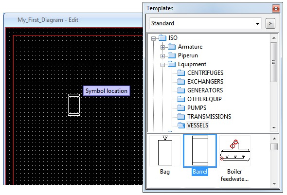
Select Templates > ISO > Equipment > VESSELS.
-
Double-click Barrel.
Do not place the vessel to the drawing yet.
-
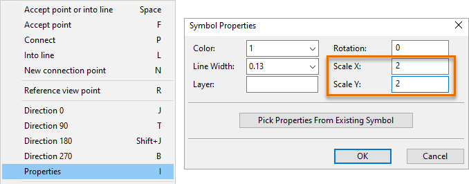
Right-click to bring out a context menu that is available when you are inserting equipment, armatures, or instruments.
-
Select Properties or press I for a shortcut. The Symbol Properties dialog opens.
-
For Scale X and Scale Y, enter 2 as the value to double the dimensions of the vessel.
-
Click OK.
-
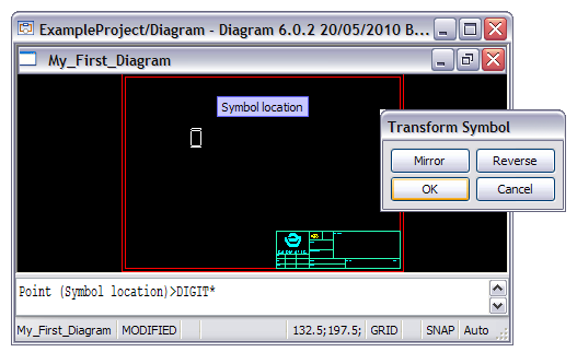
Move the vessel near the upper left corner of the sheet.
-
Left-click to place the vessel.
-
Click OK to proceed. The Transform Symbol dialog opens. You can mirror the vessel or reverse its direction. However, you do not need to do that now.
-
Click OK.
-
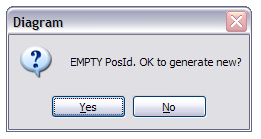
Click Yes to generate a position ID for the vessel. The Edit Equipment Data dialog appears.
Editing equipment data
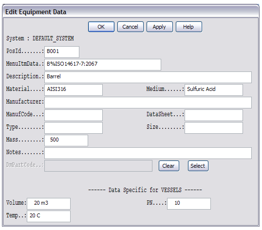
Inserting the drawing symbol is plain drafting. The component database now comes into play. The database is shared by all designers and diagrams within a project and therefore is not a part of this particular diagram you are designing.
The Edit Equipment Data dialog gives you a view to the component database. It shows you all the data fields that have been configured to exist for a component of the class of the piece of equipment you just placed (in this case, the vessel).
The fields are mostly in an initialized state. For PosId, you generated the value earlier. The Description is also filled in with the information of the piece of equipment you placed.
You can edit the data in any of the fields.
If you edit PosId and click OK, the program checks that the position ID you entered is unique.
-
If it is, the program saves the database record of the vessel into the database.
-
If it is not, the program cannot save the database record, and you have to enter a new position ID. You can select one from the list of free position IDs that opens.
If needed, you can later open the database record for editing. Select Modify Data > Edit.
At this point, it suffices to accept the suggested values.
Do the following:
-
Click OK.
Now, the vessel outline is no longer just a drawing symbol: it has a database record associated with it, making it a diagram object.
Note: It depends on your current settings whether or not the program opens the Edit Equipment Data window every time you insert a new component. You can also configure Diagram so that it "silently" creates the database record without a position ID, letting you fill it in together with other data later by selecting Settings > Insert). In fact, most designers may feel this approach more convenient.
The program now automatically inserts the label for the vessel. The label, which you can by now see on the drawing window along with a cross-hair cursor, contains the position id.
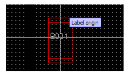
Do the following:
-
Position the label inside the vessel.
-
Left-click to place the label.
You have completed inserting the first component into your first diagram.
The program remains in the Insert Component mode, having selected a vessel similar to the one you just inserted. This is to make inserting a number of similar components a smooth process. You do not need to add another component, so exit the inserting mode and save the diagram.
Do the following:
-
Press Esc to exit the inserting mode.
-
Select File > Save or press Ctrl+S to save the diagram.
You have now inserted a vessel on the diagram and given it a label.