Export the document
When you publish a drawing (see Publishing documents), a DWG file of the drawing is exported, and this drawing file is stored in the drawing publication data.
For published documents, you can create an export of the latest publication. For both published and unpublished documents, you can export the current (edited) version of the document.
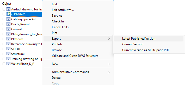
It is usually recommended to export the Latest Published Version, and you should only export unofficial work copies from the editable drawing.
While it is not mandatory for this tutorial, you might need to change the colors of the export at some point. An admin should commit the following changes before exporting the drawing, using the example from the image below:
Do the following:
-
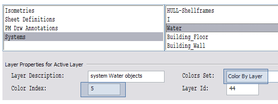
In the Project Database, select the folder Example Project/Configuration/Common/Drawing export configuration.
- Change the color values for each of the layers you want.
-
Restart Plant Modeller to implement these changes.
In Plant Modeller, you have to select the Line Attribute Style for views. Drawing views use line (attribute) styles to define line type for visible, center and hidden lines for objects you see in a view.
Do the following:
-
Select Views > Select Line Attribute Style.
-
Select General Layout.
-
Click OK.
-
Select the views that you want to assign the line style to.
-
Click OK.
In the picture below you can see that General Layout uses Layer Style named Each system to its own layer. In the Layer Style, each system is mapped to a layer according to the system name. If a system uses center lines (like the Water system for pipelines), you can map center lines to a different layer as Water_CL in our example.
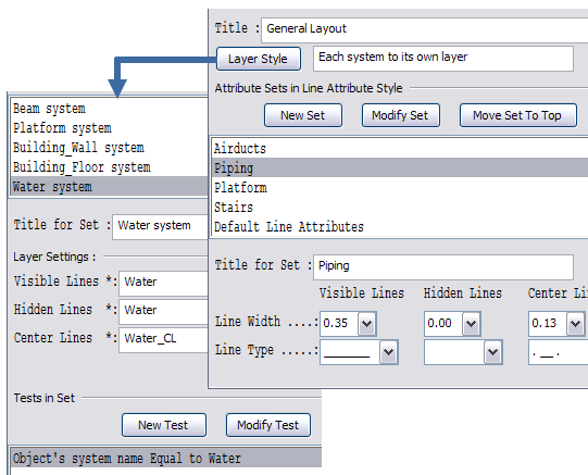
In Attribute Sets in Line Attribute Style, you can define how to present line types for each set of objects. As you can see in the picture, the center lines for Piping are thin (0.13) dash-dot lines while the visible lines are thick (0.35) continuous lines.
If you take a look at Tests in Set, you find out that this set contains all pipes and standard components except those ones which belong to systems Platform, Railing, or Stairs. That is because some objects in those systems are also pipe or standard components, but they are wanted to be exported in a set named Platform or Stairs.
Do the following:
-
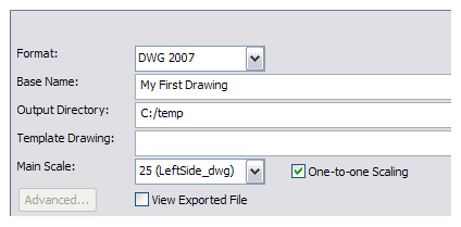
Select Export Document.
-
Select a convenient file format and output directory.
-
In the Main Scale drop-down menu, select a scale according to the view in the active page.
-
Select One-to-one Scaling to scale the drawing according to the main scale.
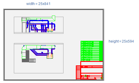
In the example the scale factor is 25, so the exported drawing size is 25x841 and 25x594 if the sheet size was A1. With the option unselected, the drawing size is sheet size, so 841x594.
In the picture below, you can see the exported drawing. Notice that the color of the platform and the stairs is gray (set in the drawing export configuration) and the line type is continuous and thin (set in line attribute style). Water system objects are blue and the centerlines are set in a layer named Water_CL.