Pipeline 03
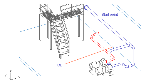
In this exercise, you start the pipeline from the run pipe with a branch and end it at the pump suction connection. You learn how to locate the start point by means of the plane CL (Y coordinate) and a connection point (X and Z coordinate) of the run pipe.
Do the following:
-
Select Piping > Route pipe.
-
Move the cursor between the flanges at the end of the run pipe.
-
Press Q to lock the cursor to the connection.
-
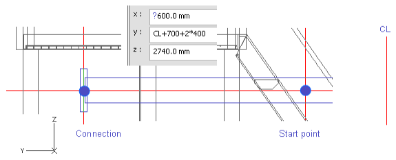
Press Y to define the Y coordinate of the start point.
-
Enter CL+700+2*400 as the value.
-
Click OK.
This time, do not press Space to accept the start point.
Note: You can also press F11 or Shift+C to lock the cursor to the centerline of the run pipe. That also sets the x and the z coordinates for the branch. It is not necessary to lock the cursor to centerline before branching. However, it is important to move cursor inside the run pipe, and press C to navigate the start point instead of using X, Y, or Z. That is because pressing C locks the cursor but pressing X, Y, or Z does not.
-
Right-click, and select Create branch.
-
Select the run pipe.
Because the cursor is inside the run pipe, it is highlighted.
-
Press Enter to accept the selection.
-
Enter the values as shown in the picture below.

-
Click Done.
-
Set the direction to the negative Z axis in one of the following ways:
-
Right-click, and select Negative Z-axis.
-
Press Alt+Ctrl+Z.
-
Press the Down arrow key and Space.

-
-
Press Shift+A to unlock the cursor.
-
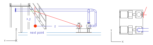
Move the cursor near the second pump suction connection to locate the Z coordinate.
You have already defined the direction to be parallel to the negative Z axis, so the X and Y coordinates are already defined.
-
Press Q to lock the cursor to the connection.
-
Press Space to accept the point.
-
Move the cursor near the end of the pipe.
-
Press W to lock the cursor to the nearest geometry point.
This ensures that the Y and Z coordinates are the same at the start and the end points of the next pipe segment.
If you have locked the cursor to a wrong location, press 5 and 6 to release it.
-
Press D to define the relative movement from the end point of the pipe.
-
For dx, enter -400 as the value.
-
Click OK to accept the coordinates.
-
Press Space to accept the point.

-
Move the cursor to the direction you want to route the next pipe segment.
This means that the angle for Fii you set later is already almost correct.
-
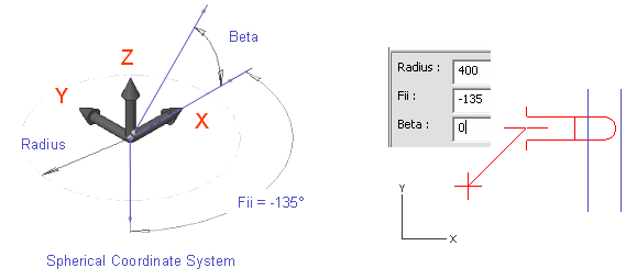
Press S to set spherical coordinates.
-
For Radius, enter 400 as the value.
The segment has to be long enough to have an elbow.
-
For Fii, enter -135 as the value.
-
For Beta, enter 0 as the value, because the pipe passes parallel to the XY plane.
-
Click OK.
-
Press Space.
-
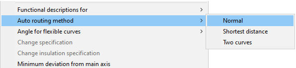
Right-click, and select Auto routing method > Normal.
Now, because there is a flange at the connection point, the direction of the last pipe segment is set according to the direction of that flange.
-
Move the cursor near the pump suction connection.
-
Press Q to lock the cursor to the connection.
-
Press P to connect.
-
Click Yes to accept the connection point.
-
Click Yes to accept the pipeline.
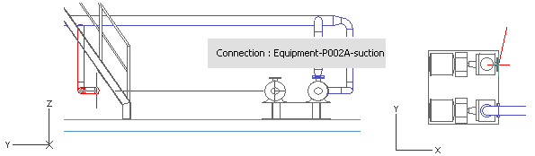
You have now routed a pipe that starts at the run pipe with a branch and ends at the second pump's suction connection.